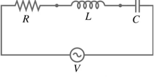
The impedance of an RLC Series circuit refers to the total opposition or resistance to the flow of alternating current (AC) in the circuit. It combines the effects of resistance (R), inductance (L), and capacitance (C) present in the circuit. The Impedance Calculator is a tool to calculate the Impedance of the circuit.
RLC Circuit Impedance Calculator
Z = √[(R^2) + (Xl – Xc)^2]
where:
- Z is the impedance of the circuit,
- R is the resistance of the circuit,
- Xl is the inductive reactance, which is the opposition to the flow of current due to inductance,
- Xc is the capacitive reactance, which is the opposition to the flow of current due to capacitance.
The inductive reactance (Xl) and capacitive reactance (Xc) can be calculated as follows:
Xl = 2πfL
Xc = 1 / (2πfC)
where:
- f is the frequency of the AC signal applied to the circuit,
- L is the inductance of the circuit,
- C is the capacitance of the circuit.
The impedance of an RLC circuit depends on the frequency of the AC signal and the values of resistance, inductance, and capacitance in the circuit. By considering the values of these components, the impedance can be determined, providing valuable information about the circuit’s behavior, such as current and voltage relationships and the phase difference between them.
The angle associated with the impedance of an RLC circuit represents the phase relationship between the current and voltage in the circuit. It is denoted by the symbol φ and is measured in radians or degrees.
The angle φ is determined by the relative values of the inductive reactance (Xl) and capacitive reactance (Xc) in the circuit. The relationship between Xl and Xc determines whether the circuit is primarily inductive or capacitive.
If Xl > Xc (inductive dominance): In this case, the circuit is primarily inductive, and the angle φ is positive. The current lags behind the voltage, and the phase angle is considered as a positive value.
If Xl < Xc (capacitive dominance): In this case, the circuit is primarily capacitive, and the angle φ is negative. The current leads the voltage, and the phase angle is considered as a negative value.
If Xl = Xc (resonance or balanced condition): In this case, the circuit is in a balanced condition, and the angle φ is zero. The current and voltage are in phase with each other.
The angle φ can be calculated using the formula:
φ = arctan((Xl – Xc) / R)
where:
- φ is the phase angle,
- Xl is the inductive reactance,
- Xc is the capacitive reactance,
- R is the resistance of the circuit.
The angle φ provides information about the phase relationship between the current and voltage in the RLC circuit. It is an essential parameter in AC circuit analysis and can help determine the behavior and characteristics of the circuit, including power factor, resonance conditions, and overall circuit performance.
Important Links