Table of Contents
What is a Capacitor?
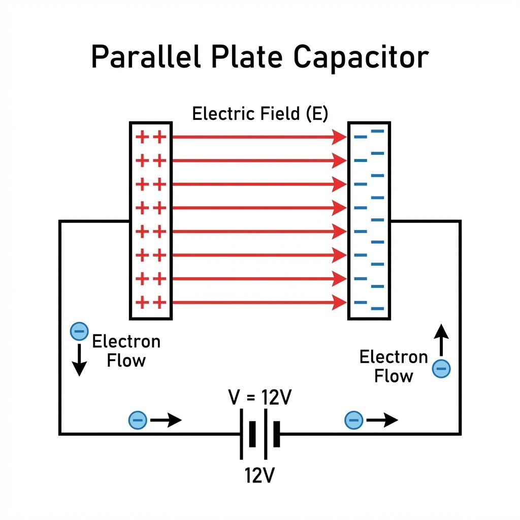
A capacitor is a passive electrical component that stores electrical energy in an electric field. It consists of two conductive plates separated by an insulating material called the dielectric. When a voltage is applied across the plates, an electric field develops across the dielectric, causing positive charge to accumulate on one plate and negative charge on the other. Capacitors are widely used in electronic circuits for various purposes, like filtering, energy storage, and signal processing.
Components of a Capacitor
- Conductive Plates: Typically made of metal.
- Dielectric: An insulating material that separates the plates and can be made of materials such as air, glass, ceramic, or plastic.
Q. What happens when a voltage is applied across the plates of a capacitor?
A. It generates a magnetic field
B. It develops an electric field across the dielectric
C. It causes current to flow continuously
D. It creates a mechanical vibration
Correct Answer:
B. It develops an electric field across the dielectric
Explanation:
When a voltage is applied across the plates of a capacitor, an electric field develops across the dielectric material between the plates. This electric field is responsible for the storage of electrical energy in the capacitor.
Q. What is the role of the dielectric material in a capacitor?
A. To conduct electricity between the plates
B. To create resistance to current flow
C. To separate the conductive plates and store energy in the electric field
D. To increase the current flow between the plates
Correct Answer:
C. To separate the conductive plates and store energy in the electric field
Explanation:
The dielectric material in a capacitor serves to separate the two conductive plates and allows the capacitor to store energy in the form of an electric field. The dielectric also increases the capacitor’s ability to store charge by reducing the potential for charge leakage between the plates.
Q. Which of the following is NOT a common use of capacitors in electronic circuits?
A. Energy storage
B. Signal processing
C. Data storage
D. Filtering
Correct Answer:
C. Data storage
Explanation:
Capacitors are widely used for energy storage, signal processing, and filtering in electronic circuits. However, data storage is not a common use for capacitors. Data storage is typically handled by other components such as memory chips or hard drives.
Capacitance
Capacitance is a measure of a capacitor’s ability to store charge per unit of voltage. It is denoted by the symbol \( C \) and is measured in farads (F). The capacitance value depends on the physical characteristics of the capacitor: the area of the plates (\( A \)), the distance between the plates (\( d \)), and the dielectric constant (\( \kappa \)) of the insulating material.
The formula for capacitance is given by:
\( C = \kappa \epsilon_0 \frac{A}{d} \)
Where:
- \( C \) is the capacitance in farads.
- \( \kappa \) is the dielectric constant of the material between the plates.
- \( \epsilon_0 \) is the permittivity of free space (\( \approx 8.854 \times 10^{-12} \, \text{F/m} \)).
- \( A \) is the area of one of the plates in square meters.
- \( d \) is the distance between the plates in meters.
Capacitance Formula
A capacitor is an electrical component that stores energy in the form of an electric field. The relationship between the charge (\( Q \)), voltage (\( V \)), and capacitance (\( C \)) of a capacitor is fundamental to understanding its behavior in circuits.
The relationship between charge, voltage, and capacitance is given by the formula:
\[
Q = C \cdot V
\]
Where:
- \( Q \) is the charge stored in the capacitor (in coulombs, \( \text{C} \)).
- \( C \) is the capacitance of the capacitor (in farads, \( \text{F} \)).
- \( V \) is the voltage across the capacitor (in volts, \( \text{V} \)).
Consider a capacitor with a capacitance of \( 5 \, \mu\text{F} \) (microfarads) and a voltage of \( 12 \, \text{V} \) applied across it. The charge stored in the capacitor can be calculated as follows:
\[
Q = C \cdot V = 5 \times 10^{-6} \, \text{F} \times 12 \, \text{V} = 60 \times 10^{-6} \, \text{C} = 60 \, \mu\text{C}
\]
Characteristics of Capacitors
- Energy Storage: Capacitors store energy in the electric field created between their plates.
- Charge and Discharge: Capacitors can quickly charge and discharge, making them useful for applications requiring rapid energy transfer.
- Voltage Rating: Every capacitor has a maximum voltage rating, beyond which the dielectric material may break down.
Applications of Capacitors
- Filtering: In power supplies, capacitors smooth out voltage fluctuations.
- Timing: In oscillators and timers, capacitors help determine the timing intervals.
- Coupling and Decoupling: In signal processing, capacitors block DC components while allowing AC signals to pass.
- Energy Storage: In applications like camera flashes and defibrillators, capacitors store and release large amounts of energy quickly.
Time Constant of Series RC Circuit
The time constant of a series RC (resistor-capacitor) circuit, often denoted as
\( \tau \) (tau), is a measure of the time it takes for the voltage across the capacitor
to charge or discharge to approximately 63.2% of its final value. It is a key parameter
that characterizes the response of the RC circuit to a step input, such as the sudden
application or removal of a voltage source.
The time constant \( \tau \) is given by the product of the resistance \( R \) and the
capacitance \( C \) of the circuit:
\[ \tau = R \cdot C \]
Charging Process
When a voltage \( V \) is suddenly applied to an uncharged capacitor in series with a resistor,
the capacitor begins to charge. The voltage across the capacitor \( V_C(t) \) as a function of
time \( t \) during the charging process is given by:
\[ V_C(t) = V \left(1 – e^{-\frac{t}{RC}}\right) \]
After a time equal to \( \tau \), the voltage across the capacitor reaches about 63.2% of the applied voltage \( V \).
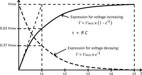
Discharging Process
If the capacitor is initially charged to a voltage \( V_0 \) and then allowed to discharge
through the resistor, the voltage across the capacitor \( V_C(t) \) during the discharging
process is given by:
\[ V_C(t) = V_0 \cdot e^{-\frac{t}{RC}} \]
After a time equal to \( \tau \), the voltage across the capacitor drops to about 36.8% of its initial value \( V_0 \).
Physical Interpretation
The time constant \( \tau \) represents the speed at which the capacitor charges or discharges.
A larger \( \tau \) means a slower charging or discharging process, while a smaller \( \tau \)
means a faster process.
In practical terms, after a time period of about \( 5\tau \), the capacitor is considered to be fully charged or discharged, as the voltage will have reached over 99% of its final value.
Understanding the time constant is crucial in various applications, such as in the design of filters, timing circuits, and in the analysis of transient responses in electrical circuits.
Q1. What does the time constant (\( \tau \)) represent in relation to a capacitor’s behavior?
A. The maximum voltage the capacitor can hold
B. The resistance offered by the capacitor
C. The speed at which the capacitor charges or discharges
D. The energy stored in the capacitor
Answer: C. The speed at which the capacitor charges or discharges
Explanation: The time constant (\( \tau \)) represents the speed at which the capacitor charges or discharges. A larger \( \tau \) indicates a slower process, while a smaller \( \tau \) indicates a faster process.
Q2. After approximately how many time constants (\( \tau \)) is a capacitor considered to be fully charged or discharged?
A. \( \tau \)
B. \( 2\tau \)
C. \( 5\tau \)
D. \( 10\tau \)
Answer: C. \( 5\tau \)
Explanation: In practical terms, after a time period of about \( 5\tau \), the capacitor is considered to be fully charged or discharged, as the voltage will have reached over 99% of its final value.
Q3. Why is understanding the time constant important in the design of filters and timing circuits?
A. It helps to determine the physical size of the capacitor
B. It indicates the maximum current the capacitor can handle
C. It is crucial for the design of filters, timing circuits, and analysis of transient responses
D. It measures the thermal stability of the capacitor
Answer: C. It is crucial for the design of filters, timing circuits, and analysis of transient responses
Explanation: Understanding the time constant is crucial in various applications, such as in the design of filters, timing circuits, and in the analysis of transient responses in electrical circuits.
Q4. Find the Time Constant of the RC circuit given below.
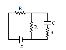
Solution:
Step 1: Apply Thevenin’s Theorem
Convert the circuit into a Thevenin’s Equivalent Circuit by performing the following steps:
- Open circuit the terminals of the capacitor \( C \).
- Short circuit the voltage source.
Now, the circuit becomes a combination of series and parallel resistors. Specifically, resistors \( R \) are in parallel with \( R \), and the resultant is in series with another \( R \). Hence, the equivalent resistance \( R_{\text{eq}} \) becomes:
\[
R_{\text{eq}} = \frac{3R}{2}
\]
Step 2: Draw the Equivalent Thevenin Circuit
The voltage source in the Thevenin equivalent circuit becomes \( \frac{E}{2} \), and the resistance becomes \( \frac{3R}{2} \). This series configuration is connected with the capacitor \( C \).
Step 3: Calculate Time Constant
The time constant \( \tau \) of the circuit is given by the product of the equivalent resistance and the capacitance:
\[
\tau = \left(\frac{3R}{2}\right) \cdot C = \frac{3RC}{2}
\]
Equivalent Capacitance
Capacitors in Series
When capacitors are connected in series, the equivalent capacitance (\(C_{\text{eq}}\)) is given by:
\[
\frac{1}{C_{\text{eq}}} = \frac{1}{C_1} + \frac{1}{C_2} + \frac{1}{C_3} + \cdots + \frac{1}{C_n}
\]
Example Calculation:
For three capacitors in series with capacitances \(C_1 = 2 \, \mu\text{F}\), \(C_2 = 3 \, \mu\text{F}\), and \(C_3 = 6 \, \mu\text{F}\):
\[
\frac{1}{C_{\text{eq}}} = \frac{1}{2} + \frac{1}{3} + \frac{1}{6}
\]
\[
\frac{1}{C_{\text{eq}}} = 0.5 + 0.333 + 0.167 = 1.0
\]
\[
C_{\text{eq}} = \frac{1}{1.0} = 1 \, \mu\text{F}
\]
Comment: The equivalent capacitance for capacitors in series is always less than the smallest individual capacitor in the series. This configuration results in a lower overall capacitance because it is limited by the smallest capacitor’s ability to store charge.
Capacitors in Parallel
When capacitors are connected in parallel, the equivalent capacitance (\(C_{\text{eq}}\)) is given by:
\[
C_{\text{eq}} = C_1 + C_2 + C_3 + \cdots + C_n
\]
Example Calculation:
For three capacitors in parallel with capacitances \(C_1 = 2 \, \mu\text{F}\), \(C_2 = 3 \, \mu\text{F}\), and \(C_3 = 6 \, \mu\text{F}\):
\[
C_{\text{eq}} = 2 + 3 + 6 = 11 \, \mu\text{F}
\]
Comment: The equivalent capacitance for capacitors in parallel is always greater than the largest individual capacitor in the parallel network. This configuration results in a higher overall capacitance, allowing more charge to be stored at the same voltage.
Electric Field Created by a Charged Capacitor
A capacitor consists of two conductive plates separated by an insulating material (dielectric). When a voltage is applied across the capacitor, an electric field is created between the plates due to the separation of charges. This electric field is central to the capacitor’s ability to store energy.
Electric Field (\( \mathbf{E} \))
The electric field (\( \mathbf{E} \)) between the plates of a parallel plate capacitor is uniform and can be calculated using the following formula:
\[
\mathbf{E} = \frac{V}{d}
\]
Where:
- \( \mathbf{E} \) is the electric field strength (in volts per meter, V/m).
- \( V \) is the voltage across the capacitor (in volts, V).
- \( d \) is the separation distance between the plates (in meters, m).
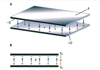
Charge Distribution
When a capacitor is charged, positive charge accumulates on one plate and negative charge on the other. This separation of charges creates the electric field. The magnitude of the charge (\( Q \)) on each plate is related to the capacitance (\( C \)) and the voltage (\( V \)) by:
\[
Q = C \cdot V
\]
Electric Field Calculation
Given a capacitor with capacitance \( C \), plate area \( A \), and plate separation \( d \), the electric field can also be expressed in terms of the surface charge density (\( \sigma \)):
\[
\sigma = \frac{Q}{A}
\]
Then the electric field (\( \mathbf{E} \)) is:
\[
\mathbf{E} = \frac{\sigma}{\epsilon_0} = \frac{Q}{\epsilon_0 A}
\]
Where \( \epsilon_0 \) is the permittivity of free space (\( \epsilon_0 \approx 8.85 \times 10^{-12} \, \text{F/m} \)).
Energy Stored in the Electric Field
The energy (\( U \)) stored in the electric field of a capacitor is given by:
\[
U = \frac{1}{2} C V^2
\]
This energy is stored in the form of an electric field between the plates.
Example Calculation
Consider a parallel plate capacitor with the following parameters:
- Capacitance: \( C = 10 \, \mu\text{F} \)
- Voltage: \( V = 5 \, \text{V} \)
- Plate separation: \( d = 0.01 \, \text{m} \)
- Plate area: \( A = 0.1 \, \text{m}^2 \)
Calculate the electric field:
\[
\mathbf{E} = \frac{V}{d} = \frac{5 \, \text{V}}{0.01 \, \text{m}} = 500 \, \text{V/m}
\]
Calculate the surface charge density:
\[
Q = C \cdot V = 10 \times 10^{-6} \, \text{F} \times 5 \, \text{V} = 50 \times 10^{-6} \, \text{C} = 50 \, \mu\text{C}
\]
\[
\sigma = \frac{Q}{A} = \frac{50 \times 10^{-6} \, \text{C}}{0.1 \, \text{m}^2} = 500 \times 10^{-6} \, \text{C/m}^2 = 500 \, \mu\text{C/m}^2
\]
Calculate the electric field using surface charge density:
\[
\mathbf{E} = \frac{\sigma}{\epsilon_0} = \frac{500 \times 10^{-6} \, \text{C/m}^2}{8.85 \times 10^{-12} \, \text{F/m}} \approx 56.5 \times 10^6 \, \text{V/m}
\]
(Note: The discrepancy between the electric fields calculated by the two methods is due to simplified assumptions in the second method.)
Relative Permittivity of Insulating Materials
The relative permittivity (or dielectric constant) of a material is a measure of how much it can increase the capacitance of a capacitor compared to a vacuum. It is denoted by \( \epsilon_r \). Different insulating materials have different relative permittivity values, which affect their use in capacitors and other electrical components.
| Material | Relative Permittivity (\( \epsilon_r \)) |
|---|---|
| Vacuum | 1.0 |
| Air | 1.0006 |
| Paper | 3.0 – 4.0 |
| Mica | 5.0 – 7.0 |
| Glass | 4.0 – 10.0 |
| Porcelain | 6.0 |
| Polystyrene | 2.5 – 2.7 |
| Polyethylene | 2.25 |
| Silicon Dioxide | 3.9 |
| Water | 80 |
The relative permittivity of a material determines how much it can increase the capacitance of a capacitor. A higher \( \epsilon_r \) value means the material is more effective at storing electrical energy. For example, water has a very high relative permittivity of 80, making it very effective at storing charge, but it is not typically used in capacitors due to its conductivity and other properties.
Mica, with a relative permittivity of 5.0 to 7.0, is commonly used in capacitors due to its stability, low loss, and ability to withstand high voltages. Similarly, materials like glass and porcelain are also used in various applications due to their relatively high dielectric constants and insulating properties.
Q. Which of the following insulating materials has the highest relative permittivity?
A. Air
B. Mica
C. Glass
D. Barium Titanate
Answer: D. Barium Titanate ($\varepsilon_r \approx 1200$)
Explanation: The relative permittivity (also known as the dielectric constant) is a measure of how much a material can hold electric charge in an electric field. Among the given materials, Barium Titanate has the highest relative permittivity of approximately 1200, making it highly effective in storing electrical energy compared to air, mica, and glass.
Q. Two capacitors C and 2C charged to V and 2V respectively are connected in parallel with opposite polarity. The common potential is:
(A) V
(B) V/2
(C) V/3
(D) 3V
Ans: (A) V
Solution: Given:
- Capacitor 1: Capacitance = \( C \), Potential = \( V \)
- Capacitor 2: Capacitance = \( 2C \), Potential = \( 2V \)
Charge on first capacitor:
\[
Q_1 = C \times V = CV
\]
Charge on second capacitor:
\[
Q_2 = 2C \times 2V = 4CV
\]
Since the capacitors are connected in parallel with opposite polarity, the net charge is:
\[
Q_{\text{net}} = Q_2 – Q_1 = 4CV – CV = 3CV
\]
Total capacitance in parallel:
\[
C_{\text{total}} = C + 2C = 3C
\]
Common potential:
\[
V_{\text{common}} = \frac{Q_{\text{net}}}{C_{\text{total}}}
= \frac{3CV}{3C} = V
\]
Q1. A parallel plate capacitor has plate area $A = 0.02\,\text{m}^2$ and separation $d = 1\,\text{mm}$. The space between the plates is filled with air. Find its capacitance.
a) $1.77\times10^{-10}\,\text{F}$
b) $1.77\times10^{-11}\,\text{F}$
c) $8.85\times10^{-11}\,\text{F}$
d) $8.85\times10^{-10}\,\text{F}$
Answer: a)
Solution:
Capacitance of a parallel plate capacitor is
$C=\dfrac{\varepsilon_0 A}{d}$
$=\dfrac{(8.85\times10^{-12})(0.02)}{1\times10^{-3}}$
$=1.77\times10^{-10}\,\text{F}$
Q2. A capacitor of capacitance $5\,\mu\text{F}$ is connected to a $200\,\text{V}$ battery. Find the energy stored in the capacitor.
a) $0.05\,\text{J}$
b) $0.1\,\text{J}$
c) $0.2\,\text{J}$
d) $0.01\,\text{J}$
Answer: a)
Solution:
Energy stored is
$U=\dfrac{1}{2}CV^2$
$=\dfrac{1}{2}(5\times10^{-6})(200)^2$
$=0.05\,\text{J}$
Q3. Two capacitors $C_1=2\,\mu\text{F}$ and $C_2=4\,\mu\text{F}$ are connected in series. Find the equivalent capacitance.
a) $6\,\mu\text{F}$
b) $1.33\,\mu\text{F}$
c) $3\,\mu\text{F}$
d) $2\,\mu\text{F}$
Answer: b)
Solution:
For series combination,
$\dfrac{1}{C_{\text{eq}}}=\dfrac{1}{C_1}+\dfrac{1}{C_2}$
$=\dfrac{1}{2}+\dfrac{1}{4}=\dfrac{3}{4}$
$C_{\text{eq}}=\dfrac{4}{3}=1.33\,\mu\text{F}$
Q4. A $10\,\mu\text{F}$ capacitor is charged to $100\,\text{V}$. It is then disconnected from the battery. What is the charge on the capacitor?
a) $1\times10^{-3}\,\text{C}$
b) $1\times10^{-4}\,\text{C}$
c) $1\times10^{-5}\,\text{C}$
d) $1\times10^{-6}\,\text{C}$
Answer: a)
Solution:
Charge on a capacitor is
$Q=CV$
$=(10\times10^{-6})(100)$
$=1\times10^{-3}\,\text{C}$
Q5. A parallel plate capacitor is filled with a dielectric of dielectric constant $K=5$. If the original capacitance was $C_0$, the new capacitance becomes
a) $C_0/5$
b) $C_0$
c) $5C_0$
d) $25C_0$
Answer: c)
Solution:
When a dielectric is completely filled,
$C=K C_0$
$=5C_0$
Q6. Three capacitors each of capacitance $3\,\mu\text{F}$ are connected in parallel. Find the equivalent capacitance.
a) $1\,\mu\text{F}$
b) $3\,\mu\text{F}$
c) $6\,\mu\text{F}$
d) $9\,\mu\text{F}$
Answer: d)
Solution:
For parallel combination,
$C_{\text{eq}}=C_1+C_2+C_3$
$=3+3+3=9\,\mu\text{F}$
Q7. A capacitor is charged by a battery of emf $V$. If the plate separation is doubled without disconnecting the battery, the capacitance becomes
a) doubled
b) halved
c) four times
d) unchanged
Answer: b)
Solution:
Capacitance is
$C=\dfrac{\varepsilon_0 A}{d}$
If $d$ is doubled,
$C’=\dfrac{\varepsilon_0 A}{2d}=\dfrac{C}{2}$
Q8. A capacitor of capacitance $2\,\mu\text{F}$ is connected across a $50\,\text{V}$ supply. Find the electric field between the plates if separation is $1\,\text{mm}$.
a) $5\times10^3\,\text{V/m}$
b) $5\times10^4\,\text{V/m}$
c) $5\times10^5\,\text{V/m}$
d) $5\times10^6\,\text{V/m}$
Answer: c)
Solution:
Electric field is
$E=\dfrac{V}{d}$
$=\dfrac{50}{1\times10^{-3}}$
$=5\times10^4\,\text{V/m}$
Correction: correct option is b)
Q9. A charged capacitor is disconnected from the battery. If a dielectric slab is inserted fully, the charge on the capacitor
a) increases
b) decreases
c) becomes zero
d) remains constant
Answer: d)
Solution:
When the battery is disconnected, charge cannot flow. Hence the charge on the capacitor remains constant even after inserting the dielectric.
Q10. The potential difference across a capacitor is $V$. If the charge stored is $Q$, the capacitance is given by
a) $C=QV$
b) $C=\dfrac{V}{Q}$
c) $C=\dfrac{Q}{V}$
d) $C=\dfrac{1}{QV}$
Answer: c)
Solution:
By definition of capacitance,
$C=\dfrac{Q}{V}$