Table of Contents
Thevenin’s Theorem
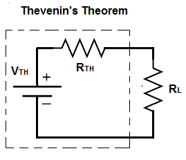
Thevenin’s Theorem is a fundamental principle in electrical engineering that simplifies the analysis of complex linear circuits. It states that any linear electrical network with voltage and current sources and resistances can be replaced by an equivalent circuit consisting of a single voltage source (\( V_{th} \)) in series with a resistance (\( R_{th} \)) connected to a load.
Steps to Apply Thevenin’s Theorem:
- Identify the Portion of the Circuit: Select the portion of the circuit to be replaced with the Thevenin equivalent. Remove the load resistor (\( R_L \)) if present.
- Calculate \( V_{th} \) (Thevenin Voltage):
- This is the open-circuit voltage across the terminals where the load resistor was connected.
- Deactivate all independent sources within the circuit (short circuit all independent voltage sources and open circuit all independent current sources), then calculate the voltage across the open terminals.
- Calculate \( R_{th} \) (Thevenin Resistance):
- This is the equivalent resistance seen from the open terminals after deactivating all independent sources.
- Short all independent voltage sources and open all independent current sources.
- Calculate the resistance looking back into the circuit from the open terminals.
- Reattach the Load Resistor: Reconnect the load resistor to the Thevenin equivalent circuit.
Example:
Consider a circuit with a voltage source \( V_s \), resistors \( R_1 \), \( R_2 \), and a load resistor \( R_L \).
- Identify the Portion: Remove \( R_L \) from the circuit.
- Calculate \( V_{th} \):
- Determine the open-circuit voltage across the terminals where \( R_L \) was connected.
- For instance, if \( R_1 \) and \( R_2 \) are in series and \( R_L \) is connected across \( R_2 \), \( V_{th} \) is the voltage across \( R_2 \).
- Calculate \( R_{th} \):
- Deactivate the independent sources (short \( V_s \)).
- Calculate the equivalent resistance seen from the open terminals. If \( R_1 \) and \( R_2 \) are in series, \( R_{th} = R_1 + R_2 \).
- Reattach the Load Resistor: Reconnect \( R_L \) to the Thevenin equivalent circuit consisting of \( V_{th} \) in series with \( R_{th} \).
Key Points:
- Linear Circuits: Thevenin’s theorem applies only to linear circuits.
- Simplification: Reduces complex circuits to a simple equivalent circuit, making analysis easier, especially for load variations.
- Versatility: Useful in both AC and DC circuit analysis, with \( V_{th} \) and \( R_{th} \) potentially being complex impedance in AC circuits.
Benefits:
- Simplifies Analysis: Reduces the need for solving complex networks multiple times for different load conditions.
- Intuitive Understanding: Provides an intuitive way to understand the behavior of a circuit at a specific pair of terminals.
Understanding Thevenin’s theorem is essential for analyzing and designing electrical circuits, as it provides a powerful method for simplifying the analysis of complex networks.