Kirchhoff’s laws are two fundamental principles in electrical circuit theory that form the foundation for analyzing complex electrical networks. Named after German physicist Gustav Kirchhoff, who formulated them in 1845, these laws are essential tools for electrical engineers and physicists working with circuits. The laws are based on the principles of conservation of charge and conservation of energy, making them universally applicable to any electrical circuit, regardless of its complexity.
Table of Contents
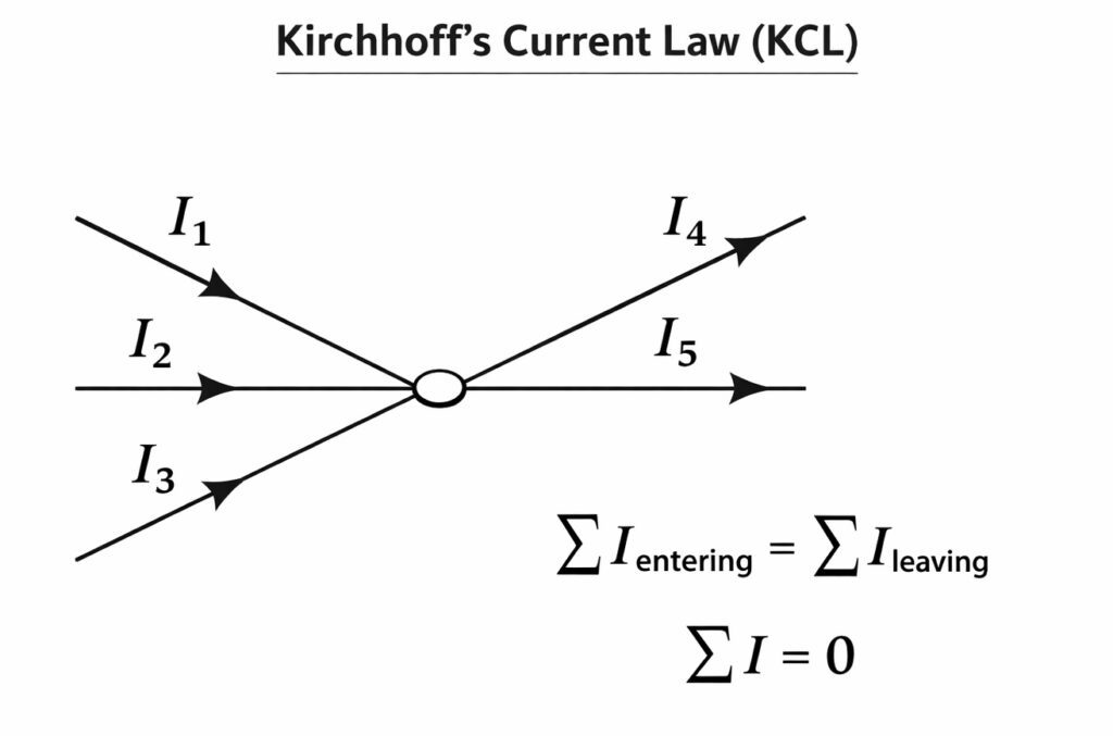
Kirchhoff’s Current Law (KCL)
Statement of KCL
Kirchhoff’s Current Law states that the algebraic sum of all currents entering and leaving a node (or junction) in an electrical circuit is equal to zero. Alternatively, it can be stated as: the sum of currents entering a node equals the sum of currents leaving that node.
Mathematical Formulation
The mathematical expression of Kirchhoff’s Current Law can be written as:
Where \(I_k\) represents the current at branch \(k\) connected to the node, and \(n\) is the total number of branches. By convention, currents entering the node are considered positive, and currents leaving the node are considered negative
Alternatively, KCL can be expressed as:
This form explicitly shows that the total current entering a node equals the total current leaving it.
Physical Basis of KCL
Kirchhoff’s Current Law is fundamentally based on the principle of conservation of electric charge. Charge cannot accumulate at a node in a circuit under steady-state conditions. Since current is the rate of flow of charge (\(I = \frac{dQ}{dt}\)), if charge were to accumulate at a node, it would require an infinite potential, which is physically impossible in practical circuits.
The law assumes that:
- No charge is created or destroyed at a node
- No charge accumulates at the node (steady-state condition)
- The circuit operates under lumped element conditions where the physical dimensions are much smaller than the wavelength of the signals
Applications of KCL
Kirchhoff’s Current Law is used extensively in:
- Analyzing complex circuit networks with multiple branches
- Finding unknown currents in circuit branches
- Simplifying circuits using nodal analysis
- Designing current divider circuits
- Analyzing parallel resistor networks
- Power system load flow analysis
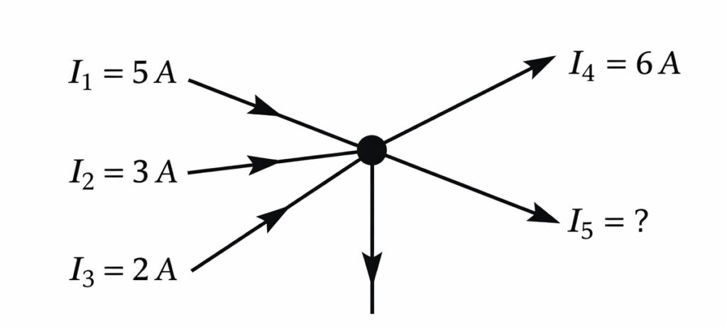
Q. In the circuit node shown below, currents entering the node are \(I_1 = 5\,A\), \(I_2 = 3\,A\), and \(I_3 = 2\,A\). Two currents leave the node: \(I_4 = 6\,A\) and \(I_5\). Find the magnitude and direction of current \(I_5\).
Solution:
Step 1: Apply Kirchhoff’s Current Law at the node.
According to KCL, the sum of currents entering the node equals the sum of currents leaving the node:
Step 2: Identify entering and leaving currents.
Currents entering: \(I_1 = 5\,A\), \(I_2 = 3\,A\), \(I_3 = 2\,A\)
Currents leaving: \(I_4 = 6\,A\), \(I_5 = ?\)
Step 3: Set up the equation.
\[5 + 3 + 2 = 6 + I_5\]
\[10 = 6 + I_5\]
Step 4: Solve for \(I_5\).
Kirchhoff’s Voltage Law (KVL)
Statement of KVL
Kirchhoff’s Voltage Law states that the algebraic sum of all voltages around any closed loop (or mesh) in an electrical circuit is equal to zero. In other words, the sum of voltage rises equals the sum of voltage drops in a closed loop.
Mathematical Formulation
The mathematical expression of Kirchhoff’s Voltage Law is:
Where \(V_k\) represents the voltage across element \(k\) in the loop, and \(n\) is the total number of elements in the closed loop. By convention, voltage rises (sources) are considered positive, and voltage drops (across resistors or other passive elements) are considered negative when traversing the loop in a chosen direction.
Alternatively, KVL can be written as:
Physical Basis of KVL
Kirchhoff’s Voltage Law is based on the principle of conservation of energy. In a closed loop, the total energy gained by a charge moving around the loop must equal the total energy lost. Since voltage is energy per unit charge (\(V = \frac{dW}{dQ}\)), the net change in voltage around a closed loop must be zero.
The electric field in a circuit is a conservative field under quasi-static conditions, meaning that the work done in moving a charge around a closed path is zero. This is a direct consequence of the conservative nature of the electrostatic field.
Sign Conventions for KVL
When applying KVL, it is crucial to maintain consistent sign conventions:
- Voltage Source: If traversing from negative to positive terminal, count it as positive (voltage rise); if from positive to negative, count it as negative (voltage drop)
- Resistor (or load): If traversing in the direction of current flow, count the voltage drop as negative; if traversing against the current, count it as positive
- Direction of traversal: Choose a direction (clockwise or counterclockwise) and maintain it consistently around the entire loop
Applications of KVL
Kirchhoff’s Voltage Law is extensively used in:
- Analyzing series circuits and voltage dividers
- Solving complex networks using mesh analysis
- Finding unknown voltages in circuit elements
- Analyzing circuits with multiple voltage sources
- Design and analysis of amplifier circuits
- Power electronics and DC-DC converter analysis
Relationship Between KCL and KVL
While Kirchhoff’s Current Law and Kirchhoff’s Voltage Law may seem independent, they are intrinsically related through the fundamental principles of charge and energy conservation. Together, they provide a complete framework for circuit analysis:
- KCL deals with currents at nodes and is based on charge conservation
- KVL deals with voltages in loops and is based on energy conservation
- Both laws work together in nodal and mesh analysis techniques
- The combination of KCL and KVL with Ohm’s law forms the foundation for solving any linear circuit
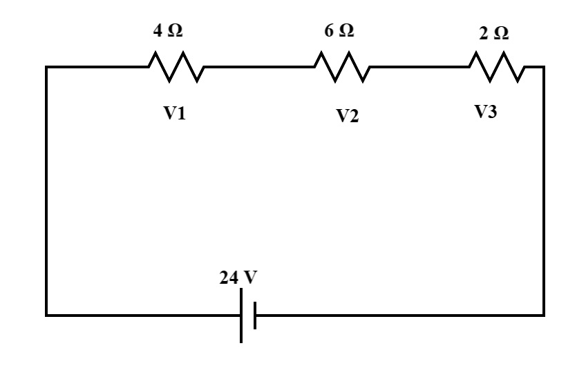
Q. A series circuit contains a voltage source \(V_s = 24\,V\), three resistors with resistances \(R_1 = 4\,\Omega\), \(R_2 = 6\,\Omega\), and \(R_3 = 2\,\Omega\). Find the current flowing through the circuit and the voltage drop across each resistor.
Solution:
Step 1: Calculate the total resistance.
Since the resistors are in series:
Step 2: Find the current using Ohm’s law.
Step 3: Calculate voltage drops across each resistor.
\[V_2 = I \times R_2 = 2 \times 6 = 12\,V\]
\[V_3 = I \times R_3 = 2 \times 2 = 4\,V\]
Step 4: Verify using KVL.
Applying KVL around the loop (taking voltage rise as positive and drops as negative):
\[24 – 8 – 12 – 4 = 0\]
\[0 = 0\]
Answer: Current \(I = 2\,A\); Voltage drops: \(V_1 = 8\,V\), \(V_2 = 12\,V\), \(V_3 = 4\,V\)
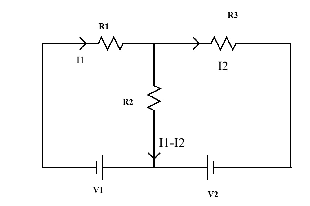
Q. A circuit has three resistors arranged in a configuration with two meshes. Mesh 1 has a \(10\,V\) source and resistors \(R_1 = 5\,\Omega\) and \(R_3 = 10\,\Omega\) (shared). Mesh 2 has a \(6\,V\) source and resistors \(R_2 = 8\,\Omega\) and \(R_3 = 10\,\Omega\) (shared). Find the current through the shared resistor \(R_3\).
Solution:
Step 1: Define mesh currents.
Let \(i_1\) = current in mesh 1 (clockwise)
Let \(i_2\) = current in mesh 2 (clockwise)
Current through \(R_3\) will be \((i_1 – i_2)\)
Step 2: Apply KVL to Mesh 1.
\[10 – 5i_1 – 10(i_1 – i_2) = 0\]
\[10 – 5i_1 – 10i_1 + 10i_2 = 0\]
\[10 – 15i_1 + 10i_2 = 0\]
Simplifying:
\[3i_1 – 2i_2 = 2 \quad \text{…(Equation 1)}\]
Step 3: Apply KVL to Mesh 2.
\[6 – 8i_2 – 10(i_2 – i_1) = 0\]
\[6 – 8i_2 – 10i_2 + 10i_1 = 0\]
\[6 + 10i_1 – 18i_2 = 0\]
Simplifying:
\[5i_1 – 9i_2 = -3 \quad \text{…(Equation 2)}\]
Step 4: Solve the system of equations.
From Equation 1:
\[i_1 = \frac{2 + 2i_2}{3}\]
Substituting into Equation 2:
\[\frac{10 + 10i_2}{3} – 9i_2 = -3\]
Multiplying through by 3:
\[10 – 17i_2 = -9\]
\[-17i_2 = -19\]
\[i_2 = \frac{19}{17} \approx 1.118\,A\]
Finding \(i_1\):
Step 5: Calculate current through \(R_3\).
Answer: The current through the shared resistor \(R_3\) is approximately \(0.29\,A\) flowing from mesh 1 to mesh 2.