An Operational Amplifier (Op-Amp) is a high-gain differential voltage amplifier widely used in analog electronic circuits. It amplifies the difference between two input voltages and produces an output voltage proportional to this difference.
Op-Amps are fundamental building blocks in signal conditioning, filtering, mathematical operations, instrumentation systems, control systems, and power electronics applications.
The output voltage of an operational amplifier is given by
$$ V_o = A (V_+ – V_-) $$
Where:
- \(V_+\) = Non-inverting input voltage
- \(V_-\) = Inverting input voltage
- \(A\) = Open-loop voltage gain
- \(V_o\) = Output voltage
Since the open-loop gain \(A\) is extremely large (typically \(10^5\) to \(10^6\)), even a very small difference between the input voltages produces a large output voltage.
Table of Contents
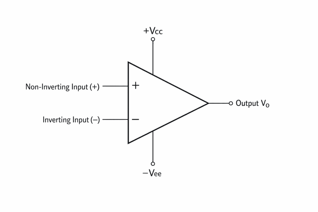
Basic Symbol of Op-Amp
An operational amplifier has two input terminals and one output terminal.
- Inverting Input (−)
- Non-Inverting Input (+)
- Output Terminal
In most circuit diagrams, the power supply terminals \(+V_{CC}\) and \(-V_{EE}\) are not shown.
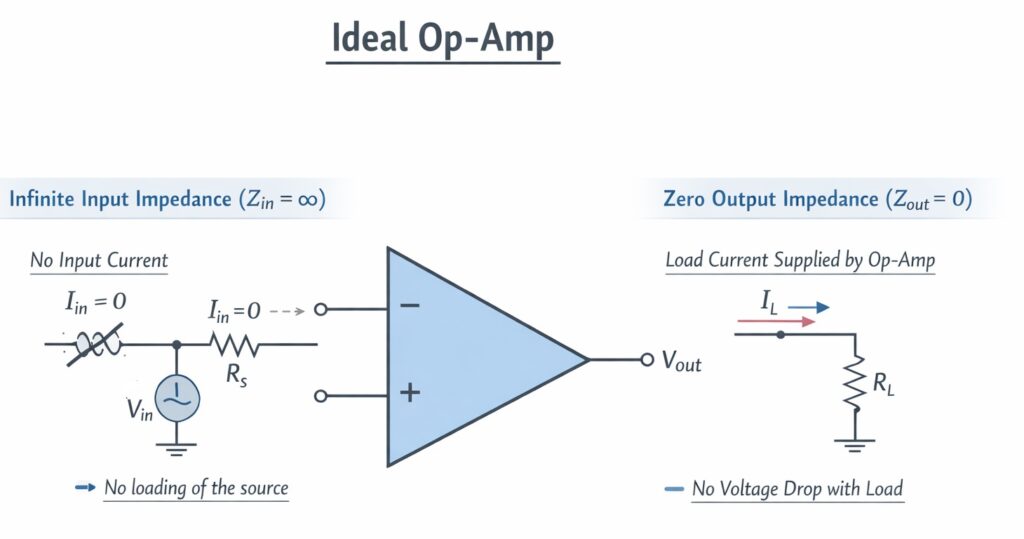
Ideal Characteristics of an Op-Amp
For circuit analysis, an operational amplifier is often assumed to be ideal. The ideal op-amp has the following characteristics:
- Infinite Open Loop Gain
$$ A \rightarrow \infty $$
- Infinite Input Impedance
$$ R_{in} \rightarrow \infty $$
This means that no current flows into the input terminals.
- Zero Output Impedance
$$ R_{out} = 0 $$
- Infinite Bandwidth
- Infinite Common Mode Rejection Ratio (CMRR)
- Infinite Slew Rate
Practical Characteristics of Op-Amp
Real operational amplifiers deviate from ideal characteristics. Typical practical values are shown below.
| Parameter | Typical Value |
|---|---|
| Open Loop Gain | \(10^5\) to \(10^6\) |
| Input Resistance | \(10^6 \Omega\) or higher |
| Output Resistance | 50–100 \( \Omega \) |
| Bandwidth | Few MHz |
| Slew Rate | 0.5 – 20 V/µs |
Op-Amp Input Modes
Differential Mode
In differential mode, the amplifier amplifies the difference between the two input voltages.
$$ V_d = V_+ – V_- $$
Common Mode
In common mode, both input terminals receive the same signal.
$$ V_c = \frac{V_+ + V_-}{2} $$
A good operational amplifier should reject common mode signals.
Common Mode Rejection Ratio (CMRR)
CMRR indicates the ability of an operational amplifier to reject common-mode signals.
$$ CMRR = \frac{A_d}{A_c} $$
Where
- \(A_d\) = Differential gain
- \(A_c\) = Common-mode gain
In decibel form,
$$ CMRR_{dB} = 20 \log_{10} \left(\frac{A_d}{A_c}\right) $$
A higher value of CMRR indicates better noise rejection capability.
What is Slew Rate of an Op-Amp?
The slew rate of an operational amplifier is defined as the maximum rate of change of the output voltage with respect to time.
It represents how quickly the output voltage of the op-amp can respond to a rapid change in the input signal.
Mathematically, the slew rate is expressed as:
\[
SR = \frac{dV_o}{dt}
\]
where
- \(SR\) = Slew Rate
- \(V_o\) = Output Voltage
- \(t\) = Time
The unit of slew rate is generally volts per microsecond (V/µs).
Physical Meaning
In a practical operational amplifier, internal circuit limitations such as the compensation capacitor and limited current in internal stages restrict the rate at which the output voltage can change. Therefore, when a large or rapidly varying input signal is applied, the output voltage cannot instantly follow the input signal.
Instead, the output voltage changes at a maximum slope determined by the slew rate of the op-amp.
Example
Consider an operational amplifier having a slew rate:
\[
SR = 0.5 \, V/\mu s
\]
This means the output voltage can change by a maximum of 0.5 volts in one microsecond.
If the output voltage needs to change from
\[
0V \rightarrow 10V
\]
The minimum time required will be
\[
t = \frac{\Delta V}{SR}
\]
\[
t = \frac{10}{0.5} = 20 \, \mu s
\]
Thus, the op-amp requires 20 microseconds to change the output from 0 V to 10 V.
Effect on Signal Waveforms
If the required rate of change of the output signal exceeds the slew rate of the op-amp, the amplifier cannot reproduce the signal accurately.
As a result, waveform distortion occurs.
For example:
- High frequency sine waves become distorted
- Sine waves may appear triangular
- Pulse signals become slower at rising and falling edges
This effect is known as slew rate distortion.
Slew Rate Requirement for Sinusoidal Signals
For a sinusoidal output voltage
\[
V_o = V_m \sin(\omega t)
\]
The required slew rate is given by
\[
SR \geq \omega V_m
\]
Since
\[
\omega = 2\pi f
\]
The expression becomes
\[
SR \geq 2\pi f V_m
\]
where
- \(f\) = Frequency of the signal
- \(V_m\) = Peak output voltage
This relation is used to determine the minimum slew rate required for distortion-free amplification of a sinusoidal signal.
Typical Slew Rate Values
- General purpose op-amp: approximately \(0.5 – 1 \, V/\mu s\)
- Precision op-amp: approximately \(1 – 10 \, V/\mu s\)
- High-speed op-amp: \(100 \, V/\mu s\) or higher
For example, the widely used 741 operational amplifier has a typical slew rate of
\[
SR \approx 0.5 \, V/\mu s
\]
Importance of Slew Rate
Slew rate is an important parameter in many electronic applications such as:
- High-frequency amplifiers
- Audio amplifier circuits
- Pulse amplifiers
- Instrumentation systems
- Data acquisition systems
A higher slew rate ensures that the amplifier can reproduce rapidly changing signals accurately without distortion.
In simple terms, the slew rate indicates how fast the output voltage of an operational amplifier can change.
A larger slew rate allows the op-amp to handle higher frequency signals and larger voltage swings effectively.
Virtual Short Concept
When negative feedback is applied to an operational amplifier, the voltages at the two input terminals become approximately equal.
$$ V_+ \approx V_- $$
This condition is known as the virtual short.
Important conclusions:
- Input currents are approximately zero.
- The two input voltages become nearly equal.
Inverting Amplifier
In this configuration, the input signal is applied to the inverting terminal through a resistor.
The output voltage is given by
$$ V_o = -\frac{R_f}{R_{in}} V_{in} $$
- Phase inversion of \(180^\circ\)
- Gain controlled by resistor ratio
- Virtual ground at the inverting terminal
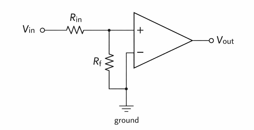
Non-Inverting Amplifier
In this configuration, the input signal is applied to the non-inverting terminal of the operational amplifier.
The voltage gain is given by
$$ A_v = 1 + \frac{R_f}{R_1} $$
- No phase inversion
- High input impedance
- Stable amplification
Applications of Op-Amp
- Summing amplifier
- Integrator
- Differentiator
- Voltage follower
- Comparator
- Active filters
- Instrumentation amplifiers