Table of Contents
Circuit Components
- AC Source: Typically represented as $v_s = V_m \sin(\omega t)$.
- Thyristor (SCR): A semiconductor switch that triggers at a specific firing angle ($\alpha$).
- Resistive Load (R): A load where current is directly proportional to voltage ($i = v/R$).
Principle of Operation
The operation is divided into the positive and negative half-cycles of the input AC signal:
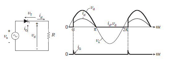
Positive Half-Cycle ($0 \le \omega t \le \pi$)
During this period, the SCR is forward-biased. However, it remains in the OFF state (forward blocking) until a trigger pulse is applied at $\omega t = \alpha$. Once triggered, the load voltage follows the input voltage until the current naturally drops to zero at $\pi$.
Negative Half-Cycle ($\pi \le \omega t \le 2\pi$)
The SCR is reverse-biased. No current flows through the load, and the output voltage $V_o$ is 0V. The SCR must be able to withstand the Peak Inverse Voltage (PIV), which is equal to $V_m$.
Mathematical Formulas
To analyze the performance of this rectifier, the following equations are used:
Average Output Voltage ($V_{dc}$):
$$V_{dc} = \frac{V_m}{2\pi} \int_{\alpha}^{\pi} \sin(\omega t) \, d(\omega t) = \frac{V_m}{2\pi} (1 + \cos \alpha)$$
Maximum Average Voltage ($V_{dc(max)}$):
Occurs when $\alpha = 0^\circ$ (acting like a diode):
$$V_{dc(max)} = \frac{V_m}{\pi}$$
RMS Output Voltage ($V_{rms}$):
$$V_{rms} = \frac{V_m}{2} \sqrt{\frac{1}{\pi} \left( \pi – \alpha + \frac{\sin 2\alpha}{2} \right)}$$
Advantages and Disadvantages
| Advantages | Disadvantages |
|---|---|
| Simple circuit design with few components. | Low efficiency (approx. 40.6%). |
| Inexpensive to implement. | High ripple content in the DC output. |
| Easy to control the output voltage. | Draws discontinuous current from the source. |