An alternator is an electrical machine that converts mechanical energy into alternating electrical energy (AC).
Table of Contents
Principle of Operation
Based on electromagnetic induction:
Whenever a conductor cuts magnetic flux, an EMF is induced in it.
- Rotor produces rotating magnetic field
- Stator conductors remain stationary
- EMF is induced in stator windings
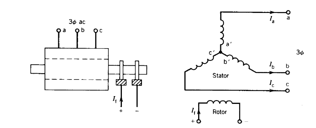
Construction
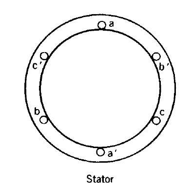
1. Stator
- Laminated core
- Three-phase armature winding
- Output terminals
2. Rotor
- Field winding
- DC excitation
- Produces magnetic field
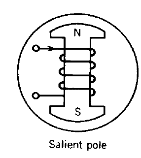
Types of Rotor
Salient Pole Rotor
- Low-speed applications
- Used in hydro plants
Cylindrical Rotor
- High-speed applications
- Used in thermal plants
Working
- DC supplied to rotor
- Rotor rotates
- Magnetic field is produced
- Field cuts stator conductors
- EMF is induced
Frequency Equation
\[
f = \frac{PN}{120}
\]
- \(f\): Frequency
- \(P\): Number of poles
- \(N\): Speed
EMF Equation
\[
E = 4.44 \, f \, \Phi \, T \, k_w
\]
- \(E\): Induced EMF
- \(f\): Frequency
- \(\Phi\): Flux per pole
- \(T\): Turns
- \(k_w\): Winding factor
Advantages
- High efficiency
- High voltage generation
- Better cooling
- Low maintenance
Applications
- Power plants
- Diesel generators
- Automobiles
- Wind power
Comparison with DC Generator
| Feature | Alternator | DC Generator |
|---|---|---|
| Output | AC | DC |
| Commutator | Not required | Required |
| Maintenance | Low | High |
| Efficiency | High | Lower |
Synchronization Conditions
- Same voltage
- Same frequency
- Same phase sequence
- Zero phase angle difference
Losses
- Copper losses
- Iron losses
- Mechanical losses
Conclusion
An alternator is a key machine for large-scale power generation due to its efficiency and reliability.