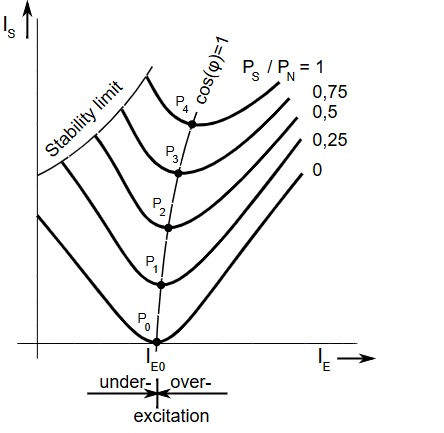
1. V curves for a synchronous motor represent the relation between
(a) Armature current and field current
(b) Field current and speed
(c) Field current and power factor
(d) Power factor and speed
Answer: (a) Armature current and field current
Explanation: The V curves of a synchronous motor show the relationship between the armature current and the field current. When the field current is varied while the motor carries a constant load, the armature current changes in a V-shaped pattern.
2. Which of the following is the reason behind an ideal synchronous motor not developing any starting torque?
(a) The relative velocity between stator and rotor mmf is large at starting
(b) The rotor is extremely heavy in these machines
(c) The stator winding is concentrated winding
(d) The rotor winding has a very high reactance
Answer: (a) The relative velocity between stator and rotor mmf is large at starting
Explanation: At the moment of starting, the stator magnetic field rotates at synchronous speed while the rotor is stationary. Because the rotor has inertia, it cannot instantly synchronize with the high-speed rotating magnetic field of the stator. This results in a large relative velocity that prevents the development of a unidirectional starting torque.
3. Determine pitch factor for winding: 36 stator slots, 4 poles, coil span 1 to 6.
(a) cos 20˚
(b) cos 40˚
(c) cos 30˚
(d) cos 80˚
Answer: (b) cos 40˚
Explanation: The pole pitch is calculated as 36 slots divided by 4 poles, which equals 9 slots. The actual coil span is from slot 1 to 6, which is 5 slots. The short pitch angle is determined by the difference of 4 slots out of 9, leading to a chording angle of 80 degrees. The pitch factor is the cosine of half this chording angle, resulting in cos 40˚.
4. The ratio of starting torque to running torque in a synchronous motor is
(a) 0
(b) 1
(c) 2
(d) infinity
Answer: (a) 0
Explanation: A synchronous motor is not self-starting and therefore has a starting torque of zero. Since the numerator of the ratio is zero, the resulting ratio of starting torque to running torque is 0.
5. Which of the following is a characteristic of ideal transformer?
(a) Zero storage magnetic energy
(b) Zero core flux
(c) Infinite core flux
(d) Large magnetizing current
Answer: (a) Zero storage magnetic energy
Explanation: An ideal transformer is assumed to have a core with infinite permeability. This implies that the magnetizing current is zero. Consequently, there is zero storage of magnetic energy within the core of an ideal transformer.
6. What type of transformer is used in AC welding?
(a) Ferrite core type
(b) Step up type
(c) Step down type
(d) Equal turns by ratio type
Answer: (c) Step down type
Explanation: AC welding requires high current at low voltage to maintain a stable arc. A step-down transformer is used to reduce the supply voltage while increasing the output current to the required level.
7. Ratio of EMF between triplex lap winding and wave winding for same power
(a) 9
(b) 4
(c) 2
(d) 1
Answer: (d) 1
Explanation: In triplex windings, the number of parallel paths increases. For a triplex lap winding, the number of paths is 3P, while for a triplex wave winding, the number of paths is 6. In a 2-pole machine, both have 6 parallel paths, so the EMF generated is equal, giving a ratio of 1.
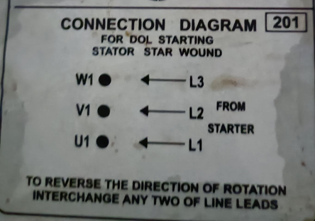
8. The number of terminals to be interchanged to reverse the direction of rotating magnetic field for a 5-phase windings and 5-phase currents are
(a) 2
(b) 3
(c) 4
(d) 5
Answer: (a) 2
Explanation: To reverse the direction of rotating magnetic field, it is sufficient to interchange any two terminals. This changes the phase sequence, thereby reversing the direction of rotation of the magnetic field in a 5-phase system.
9. A 3-phase 400 V, 50 Hz, 4 pole slip ring induction motor is excited with rated voltage and rated frequency. A centre zero ammeter is connected in rotor circuit and it has been observed that it is completing 90 oscillations per minute. What is the speed of rotor field in rpm?
(a) 25 rpm
(b) 45 rpm
(c) 50 rpm
(d) 90 rpm
Answer: (b) 45 rpm
Step 1. Calculate Synchronous Speed (\(N_s\))
The synchronous speed of the rotating magnetic field (RMF) is:
\[
N_s = \frac{120 \times f}{P}
\]
Substituting the given values:
\[
N_s = \frac{120 \times 50}{4} = 1500 \text{ rpm}
\]
Step 2: Determine Rotor Current Frequency (\(f_r\))
The rotor current frequency is:
\[
f_r = \frac{\text{Oscillations per minute}}{60}
\]
\[
f_r = \frac{90}{60} = 1.5 \text{ Hz}
\]
Step 3. Calculate Slip (\(s\))
The relation between rotor frequency and slip is:
\[
f_r = s \times f \Rightarrow s = \frac{f_r}{f}
\]
\[
s = \frac{1.5}{50} = 0.03 \; (\text{or } 3\%)
\]
Step 4. Determine Rotor Speed (\(N_r\))
\[
N_r = N_s(1 – s)
\]
\[
N_r = 1500 \times (1 – 0.03) = 1455 \text{ rpm}
\]
Step 5. Calculate Speed of Rotor Field
The speed of the rotor magnetic field with respect to the rotor is:
\[
\text{Speed} = N_s – N_r
\]
\[
\text{Speed} = 1500 – 1455 = 45 \text{ rpm}
\]
The speed of the rotor field with respect to the rotor structure is 45 rpm.
10. A 3-phase 6 pole 400 V slip ring induction motor is running at a speed of 960 rpm. What is the additional resistance required in rotor circuit to reduce the speed by 10%, if rotor resistance is 0.2 ohm?
(a) 0.48 ohm
(b) 0.68 ohm
(c) 0.88 ohm
(d) 0.28 ohm
Answer: (a) 0.48 ohm
Explanation:
Step 1. Calculate Synchronous Speed (\(N_s\))
The synchronous speed is given by:
\[
N_s = \frac{120 \times f}{P}
\]
Substituting the values:
\[
N_s = \frac{120 \times 50}{6} = 1000 \text{ rpm}
\]
Step 2. Determine Initial and Final Slips (\(s_1\) and \(s_2\))
Initial slip:
\[
s_1 = \frac{N_s – N_{r1}}{N_s} = \frac{1000 – 960}{1000} = 0.04
\]
New rotor speed after 10% reduction:
\[
N_{r2} = 960 \times (1 – 0.10) = 864 \text{ rpm}
\]
New slip:
\[
s_2 = \frac{1000 – 864}{1000} = 0.136
\]
Step 3. Relation Between Slip and Rotor Resistance
For constant torque:
\[
\frac{s_1}{R_2} = \frac{s_2}{R_{total}}
\]
where:
- \(R_{total} = R_2 + R_{ext}\)
Step 4. Calculate Total Resistance
\[
R_{total} = R_2 \times \left(\frac{s_2}{s_1}\right)
\]
\[
R_{total} = 0.2 \times \left(\frac{0.136}{0.04}\right) = 0.2 \times 3.4 = 0.68 \; \Omega
\]
Step 5. Calculate Additional Resistance
\[
R_{ext} = R_{total} – R_2
\]
\[
R_{ext} = 0.68 – 0.2 = 0.48 \; \Omega
\]
The additional resistance required in the rotor circuit is 0.48 Ω.
11. Find the voltage at \(V_o\) (assume \(V_{in} \gg V_{ref}\) and diode drop is \(V_f\))
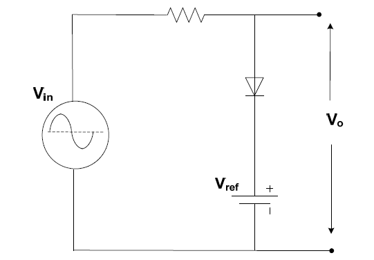
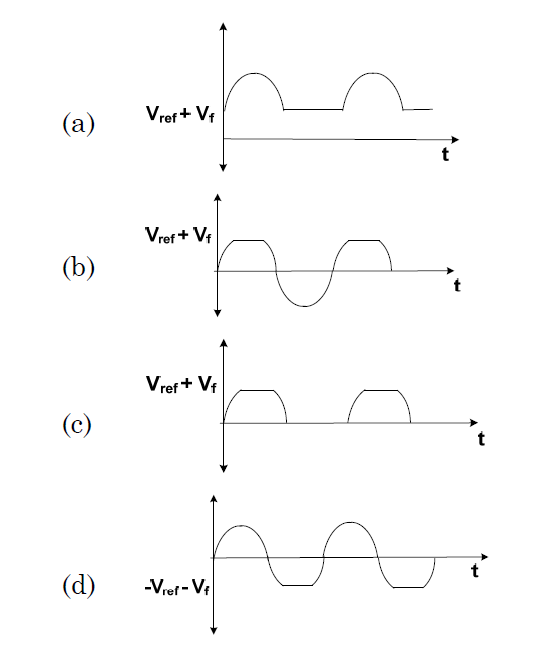
Answer: (a)
Explanation: The Output Voltage will never drop below \(V_{ref} \). Once \(V_{in} \) is more than \(V_{ref} \), the output voltage will follow the input voltage wave.
12. For a current series negative feedback amplifier, the effective output resistance
(a) Decreases
(b) Increases
(c) No change
(d) Increases and then decreases
Answer: (b) Increases
Explanation: In a current series negative feedback amplifier, the output current is sampled and fed back in series at the input. This type of feedback increases the effective output resistance, making the amplifier behave more like an ideal current source.
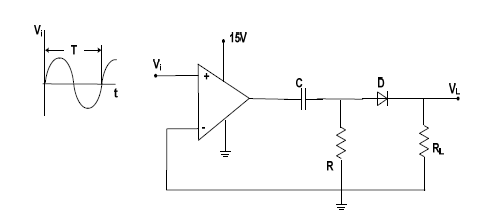
13 Find the output voltage at VL for the following circuit
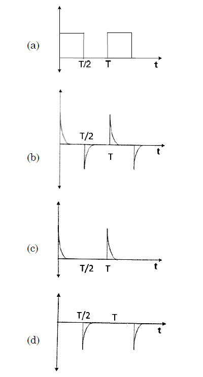
Answer: (c)
Explanation:
To determine the output voltage \(V_L\), we analyze the circuit consisting of an op-amp comparator followed by a diode-capacitor (RC) network.
1. Op-Amp Stage (Comparator)
The operational amplifier is used as a comparator:
Non-inverting terminal: \(V_{in}\)
Inverting terminal: \(0\,V\) (ground)
Operation:
If \(V_{in} > 0\):
$$
V_1 = +15\,V
$$
If \(V_{in} < 0\):
$$
V_1 = 0\,V
$$
Thus, the output \(V_1\) is a square wave switching between \(0\,V\) and \(+15\,V\) with period \(T\).
2. RC Network (Differentiator)
The square wave passes through a high-pass RC circuit (capacitor \(C\) and resistor \(R\)).
Since the time constant is small:
$$
RC \ll T
$$
The circuit behaves like a differentiator.
Output of differentiator:
At rising edge (\(t = 0, T, \dots\)) → positive spike
At falling edge (\(t = \frac{T}{2}, \frac{3T}{2}, \dots\)) → negative spike
3. Diode Action
The diode allows only positive voltages to pass to the load.
Positive spike: diode conducts → appears at output
Negative spike: diode blocks → output becomes zero
Final Output \(V_L\)
The output consists only of positive spikes at every rising edge of the square wave:
$$
V_L = \text{series of positive spikes at } t = 0, T, 2T, \dots
$$
There is no output during negative spikes due to diode blocking.
14. Find i in the following figure.
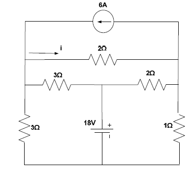
(a) 56/25 A
(b) 96/25 A
(c) 91/15 A
(d) 81/16 A
Answer: (b) 96/25 A
Explanation: Using nodal analysis or equivalent resistance method, the current distribution in the circuit can be calculated. Applying Kirchhoff laws to the given network results in the value of current i as 96/25 A.
15. The VI characteristics of a particular component is shown in Figure. Identify the component
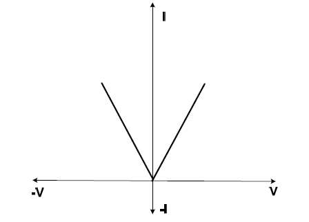
(a) Linear, passive, unilateral
(b) Linear, active, unilateral
(c) Non-linear, active, bilateral
(d) Non-linear, active, unilateral
Answer: (d) Non-linear, active, unilateral
Explanation: A device is non-linear if its VI characteristic is not a straight line. It is active if it can supply power or provide gain, and unilateral if its behavior depends on the direction of current or polarity. The given characteristics indicate a non-linear active unilateral component.
16. An 11 V pulse of 10 micro second duration is applied to the circuit in the given figure. Assuming that the capacitor is completely discharged prior to applying the pulse, the peak value of the capacitor voltage is
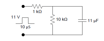
(a) 11 V
(b) 5.5 V
(c) 6.32 V
(d) 10 V
Answer: (c) 6.32 V
Explanation: The capacitor charges according to the exponential charging equation. During one time constant, the capacitor charges to about 63.2 percent of the applied voltage. For an 11 V pulse, the voltage across the capacitor becomes approximately 6.32 V.
17. What is the Norton resistance across terminals a and b for the circuit given below?
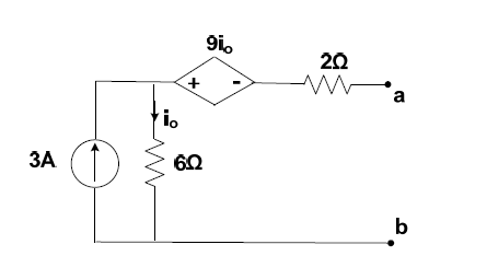
(a) 1 ohm
(b) –1 ohm
(c) 3 ohm
(d) –3 ohm
Answer: (a) 1 ohm
Explanation: The Norton resistance is equal to the Thevenin resistance seen from the terminals. By deactivating all independent sources and calculating the equivalent resistance, the value is found to be 1 ohm.
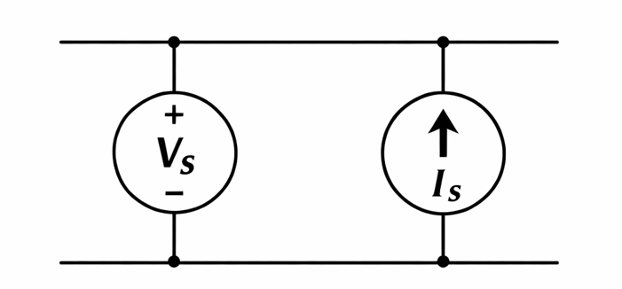
18. An ideal voltage source is connected in parallel to an ideal current source, then its combination has
(a) Thevenin equivalent only
(b) Norton equivalent only
(c) Both
(d) None
Answer: (a) Thevenin equivalent only
Explanation: An ideal voltage source maintains a constant voltage across its terminals. When connected in parallel with a current source, it dominates the circuit behavior, resulting in a valid Thevenin equivalent. However, the Norton equivalent current becomes infinite, making it impractical.
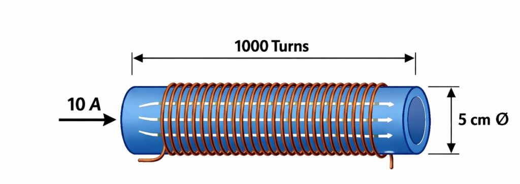
19. The energy stored in the magnetic field at a solenoid 50 cm long and 5 cm diameter wound with 1000 turns of wire carrying a current at 10 A is
(a) 0.025 joules
(b) 0.25 joules
(c) 0.5 joules
(d) 1.25 joules
Answer: (b) 0.25 joules
Explanation:
The energy stored in an inductor (solenoid) is given by:
U = \frac{1}{2} L I^2
$$
1. Given Data
- Length: \( l = 50\,\text{cm} = 0.5\,\text{m} \)
- Diameter: \( d = 5\,\text{cm} = 0.05\,\text{m} \)
- Radius: \( r = 0.025\,\text{m} \)
- Number of turns: \( N = 1000 \)
- Current: \( I = 10\,\text{A} \)
- Permeability:
$$
\mu_0 = 4\pi \times 10^{-7}\,\text{H/m}
$$
2. Inductance of Solenoid
The inductance is given by:
L = \frac{\mu_0 N^2 A}{l}
$$
Where cross-sectional area:
A = \pi r^2 = \pi (0.025)^2 = 1.9635 \times 10^{-3}\,\text{m}^2
$$
Substituting values:
L = \frac{(4\pi \times 10^{-7})(1000)^2 (1.9635 \times 10^{-3})}{0.5}
$$
L \approx 4.93 \times 10^{-3}\,\text{H} = 4.93\,\text{mH}
$$
3. Energy Stored
Using the energy formula:
U = \frac{1}{2} \times (4.93 \times 10^{-3}) \times (10)^2
$$
U = \frac{1}{2} \times 0.00493 \times 100 = 0.2465\,\text{J}
$$
Final Answer
U \approx 0.25\,\text{J}
$$
Thus, the energy stored in the magnetic field of the solenoid is approximately 0.25 Joules.
20. Which one of the following combinations of open circuit voltage and the Thevenin’s equivalent resistance represents the Thevenin’s equivalent of the circuit shown in the given figure?
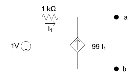
(a) 1 V, 10 ohm
(b) 1 V, 1 k ohm
(c) 1 mV, 1 k ohm
(d) 1 mV, 10 ohm
Answer: (c) 1 mV, 1 k ohm
Explanation:
Thevenin Equivalent Across Terminals a and b:
1. Find the Open Circuit Voltage (\(V_{oc}\))
Terminal a and b are open, so the current entering terminal a is zero.
The current \(I_1\) flows from the \(1\,\text{V}\) source through the \(1\,\text{k}\Omega\) resistor to ground (node b).
By Ohm’s Law:
\[
I_1 = \frac{1\,\text{V}}{1\,\text{k}\Omega} = 1\,\text{mA}
\]
The dependent current source is \(99I_1\). Since \(I_1 = 1\,\text{mA}\),
\[
99I_1 = 99\,\text{mA}
\]
Because terminals a-b are open, this \(99\,\text{mA}\) current flows through the \(1\,\text{k}\Omega\) resistor.
The open circuit voltage is:
\[
V_{oc} = I_1 \times 1\,\text{k}\Omega = 1\,\text{mA} \times 1\,\text{k}\Omega = 1\,\text{V}
\]
2. Find the Thevenin Resistance (\(R_{th}\))
Apply a test voltage \(V_x\) across terminals a-b and deactivate the independent source.
The \(1\,\text{V}\) source is replaced by a short circuit.
This makes:
\[
I_1 = 0
\]
The dependent source becomes:
\[
99I_1 = 0
\]
(acts as an open circuit)
Looking into terminals a-b, the equivalent resistance becomes:
\[
R_{th} = 10\,\Omega
\]
\[
V_{oc} = 1\,\text{V}, \quad R_{th} = 10\,\Omega
\]
21. For the circuit in the given figure, the voltage V0 is
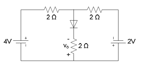 (a) 2 V
(b) 1 V
(c) –1 V
(d) None of the above
Answer: (b) 1 V
Explanation:
1. Circuit Analysis
Nodes: Let the central junction above the diode be Node \(x\) with voltage \(V_x\). The bottom rail is ground (\(0\,\text{V}\)).
Diode Assumption: Assuming the diode is ideal and forward-biased, it behaves as a short circuit. Hence,
\[
V_0 = V_x
\]
Branches:
Left branch: \(4\,\text{V}\) source in series with \(2\,\Omega\)
Middle branch: Diode + \(2\,\Omega\) resistor (output across this resistor)
Right branch: \(2\,\text{V}\) source in series with \(2\,\Omega\)
2. Applying KCL at Node \(x\)
The sum of currents leaving node \(x\) is zero:
\[
\frac{V_x – 4}{2} + \frac{V_x – 0}{2} + \frac{V_x – (-2)}{2} = 0
\]
Note: The \(2\,\text{V}\) source has its positive terminal connected to ground, so its node voltage is \(-2\,\text{V}\).
Multiply the equation by 2:
\[
(V_x – 4) + V_x + (V_x + 2) = 0
\]
\[
3V_x – 2 = 0
\]
\[
3V_x = 2 \Rightarrow V_x = \frac{2}{3}\,\text{V}
\]
3. Determining \(V_0\)
Since the diode is assumed to be a short circuit:
\[
V_0 = V_x = \frac{2}{3}\,\text{V}
\]
4. Verifying Options
\[
V_0 \approx 0.67\,\text{V}
\]
22. The phasor current through the inductance in the given circuit shown is
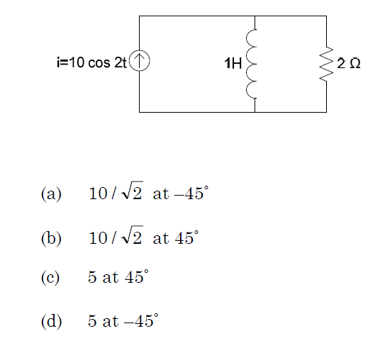
Answer: (a)
Explanation:
1. Identify Circuit Parameters
- Current source:
\[
i(t) = 10 \cos(2t)\,\text{A}
\] - Phasor form:
\[
\mathbf{I}_s = 10 \angle 0^\circ\,\text{A}
\] - Angular frequency:
\[
\omega = 2\,\text{rad/s}
\] - Inductance:
\[
L = 1\,\text{H}
\] - Resistance:
\[
R = 2\,\Omega
\]
2. Calculate Impedances
- Inductive reactance:
\[
Z_L = j\omega L = j(2)(1) = j2\,\Omega
\] - Resistive impedance:
\[
Z_R = 2\,\Omega
\]
3. Apply Current Division Rule
The current through the inductor is:
\[
\mathbf{I}_L = \mathbf{I}_s \times \left( \frac{Z_R}{Z_R + Z_L} \right)
\]
\[
\mathbf{I}_L = 10 \times \left( \frac{2}{2 + j2} \right)
\]
\[
\mathbf{I}_L = \frac{20}{2(1 + j)} = \frac{10}{1 + j}
\]
4. Convert to Polar Form
- Magnitude of denominator:
\[
|1 + j| = \sqrt{1^2 + 1^2} = \sqrt{2}
\] - Phase angle:
\[
\tan^{-1}\left(\frac{1}{1}\right) = 45^\circ
\]
Thus,
\[
\mathbf{I}_L = \frac{10 \angle 0^\circ}{\sqrt{2} \angle 45^\circ}
= \frac{10}{\sqrt{2}} \angle -45^\circ \,\text{A}
\]
\[
\mathbf{I}_L = \frac{10}{\sqrt{2}} \angle -45^\circ \,\text{A}
\]
23. Which of the signals/systems are non-causal in nature?
(A) \(y(n) = x(n^2)\)
(B) \(y(n) = (0.4)^n x(n)\)
(C) \(y(n) = \frac{x(n) + x(n-1) + x(n+1)}{3}\)
(D) \(y(n) = x(n) + x(n-4)\)
(a) Only (A)
(b) (A) & (C)
(c) (B) & (D)
(d) Only (B)
Answer: (b)
Explanation:
A system is said to be non-causal if the output at time \(n\) depends on future values of the input.
System (A):
\[
y(n) = x(n^2)
\]
For example, at \(n = 2\):
\[
y(2) = x(4)
\]
This depends on a future input, hence it is non-causal.
System (C):
\[
y(n) = \frac{x(n) + x(n-1) + x(n+1)}{3}
\]
The term \(x(n+1)\) represents a future input, so this system is non-causal.
System (B):
\[
y(n) = (0.4)^n x(n)
\]
Depends only on present input → causal.
System (D):
\[
y(n) = x(n) + x(n-4)
\]
Depends only on present and past inputs → causal.
Hence, the non-causal systems are (A) and (C).
24. For the given digital filter, evaluate \( \frac{Y(z)}{X(z)} \). Where \(p_0, p_1\) and \(d_1\) are scalars and \(z^{-1}\) represents a delay element of time.
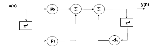
(a) \(\dfrac{p_0 + p_1 z^{-1}}{1 + d_1 z^{-1}}\)
(b) \(\dfrac{p_0 – p_1 z^{-1}}{1 + d_1 z^{-1}}\)
(c) \(\dfrac{p_0 + p_1 z^{-1}}{1 + d_1 z}\)
(d) \(\dfrac{p_0 + p_1 z}{1 + d_1 z^{-1}}\)
Answer: (a)
Explanation
The digital filter consists of two main parts: a feed-forward section and a feedback section.
Feed-forward path:
The input signal passes through two paths:
- Direct path with gain \(p_0\)
- Delayed path with gain \(p_1 z^{-1}\)
Thus, the numerator becomes:
\[
p_0 + p_1 z^{-1}
\]
Feedback path:
The output is fed back through a delay element \(z^{-1}\) with gain \(-d_1\).
In block diagram reduction, a negative feedback loop results in the denominator:
\[
1 + d_1 z^{-1}
\]
Combining feed-forward and feedback sections, the overall transfer function is:
\[
\frac{Y(z)}{X(z)} = \frac{p_0 + p_1 z^{-1}}{1 + d_1 z^{-1}}
\]
Hence, the correct answer is (a).
25. \( \frac{d}{dx}\sin^{-1}(3x – 4x^3) \)
(a) \(\dfrac{3}{\sqrt{1-x^2}}\)
(b) \(\dfrac{-3}{\sqrt{1-x^2}}\)
(c) \(\dfrac{1}{\sqrt{1-x^2}}\)
(d) \(\dfrac{-1}{\sqrt{1-x^2}}\)
Answer: (a)
Explanation
Using the identity:
\[
\sin(3\theta) = 3\sin\theta – 4\sin^3\theta
\]
Let \(x = \sin\theta\), then:
\[
3x – 4x^3 = \sin(3\theta)
\]
Thus,
\[
\sin^{-1}(3x – 4x^3) = \sin^{-1}(\sin(3\theta)) = 3\theta
\]
Since \( \theta = \sin^{-1}x \), we get:
\[
= 3\sin^{-1}x
\]
Differentiating:
\[
\frac{d}{dx}[3\sin^{-1}x] = \frac{3}{\sqrt{1-x^2}}
\]
26. The area bounded by x-axis, the curve \(y = f(x)\) and the lines \(x = 1, y = b\) is equal to \( \sqrt{b^2 + 1} – \sqrt{2} \) for all \(b > 1\), then \(f(x)\) is
(a) \(\sqrt{x-1}\)
(b) \(\sqrt{x+1}\)
(c) \(\sqrt{x^2-1}\)
(d) \(\dfrac{x}{\sqrt{1+x^2}}\)
Answer: (d)
Explanation
Given:
\[
\int_{1}^{b} f(x)\,dx = \sqrt{b^2 + 1} – \sqrt{2}
\]
By Fundamental Theorem of Calculus:
\[
f(b) = \frac{d}{db}\left(\sqrt{b^2 + 1} – \sqrt{2}\right)
\]
\[
f(b) = \frac{1}{2\sqrt{b^2+1}} \cdot 2b = \frac{b}{\sqrt{1+b^2}}
\]
Replacing \(b\) with \(x\):
\[
f(x) = \frac{x}{\sqrt{1+x^2}}
\]
27. If \(A\) is a square matrix such that
\( A(\text{Adj }A) =
\begin{bmatrix}
5 & 0 & 0 \\
0 & 5 & 0 \\
0 & 0 & 5
\end{bmatrix} \), then \( \det(\text{Adj }A) = \)
(a) 5
(b) 25
(c) 125
(d) 625
Answer: (b)
Explanation
Using the identity:
\[
A(\text{Adj }A) = |A|I
\]
Given matrix = \(5I\), so:
\[
|A| = 5
\]
For an \(n \times n\) matrix:
\[
|\text{Adj }A| = |A|^{n-1}
\]
Here \(n = 3\):
\[
|\text{Adj }A| = 5^{3-1} = 5^2 = 25
\]
28. The number of non-trivial solutions of the system
\[
x – y + z = 0
\]
\[
x + 2y – z = 0
\]
\[
2x + y + 3z = 0
\]
(a) 0
(b) 1
(c) 2
(d) 3
Answer: (a)
Explanation
For a homogeneous system, non-trivial solutions exist only if:
\[
|A| = 0
\]
Determinant:
\[
\begin{vmatrix}
1 & -1 & 1 \\
1 & 2 & -1 \\
2 & 1 & 3
\end{vmatrix}
\]
\[
= 1(6 – (-1)) – (-1)(3 – (-2)) + 1(1 – 4)
\]
\[
= 1(7) + 1(5) + 1(-3) = 7 + 5 – 3 = 9
\]
Since determinant \(\neq 0\), only trivial solution exists. Hence, number of non-trivial solutions = 0.
29. A power station has a maximum demand of 15000 kW. The annual load factor is 50% and the plant capacity factor is 40%. The reserve capacity of the plant is
(a) 5630 kW
(b) 4210 kW
(c) 3750 kW
(d) 2760 kW
Answer: (c) 3750 kW
Explanation:
1. Calculate Average Demand:
\[
\text{Average Demand} = \text{Maximum Demand} \times \text{Load Factor}
\]
\[
= 15000 \times 0.50 = 7500 \text{ kW}
\]
2. Calculate Plant Capacity:
\[
\text{Plant Capacity} = \frac{\text{Average Demand}}{\text{Plant Capacity Factor}}
\]
\[
= \frac{7500}{0.40} = 18750 \text{ kW}
\]
3. Calculate Reserve Capacity:
\[
\text{Reserve Capacity} = \text{Plant Capacity} – \text{Maximum Demand}
\]
\[
= 18750 – 15000 = 3750 \text{ kW}
\]
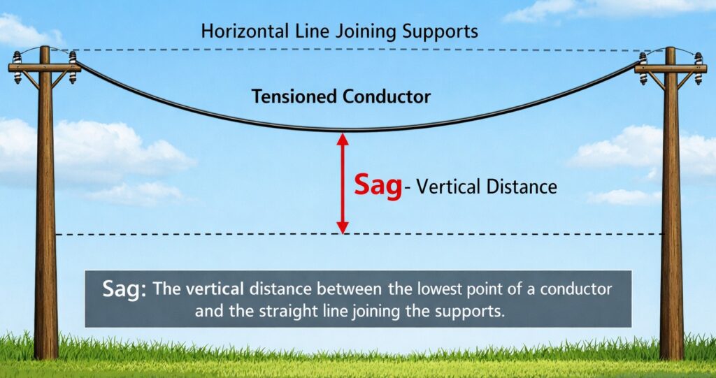
30. An overhead line has a span of 200 m, the weight of the line conductor is 0.5 kg/m. If the maximum tension in the line is 1000 kg, then the sag in the line is
(a) 1.5 m
(b) 2.0 m
(c) 2.5 m
(d) 5.0 m
Answer: (c) 2.5 m
Explanation:
Given Data
- Span length \(L = 200 \, \text{m}\)
- Weight per unit length \(w = 0.5 \, \text{kg/m}\)
- Maximum tension \(T = 1000 \, \text{kg}\)
Sag Formula
For supports at equal levels, sag is given by:
\[
S = \frac{w L^2}{8T}
\]
Calculation
\[
S = \frac{0.5 \times (200)^2}{8 \times 1000}
\]
\[
= \frac{0.5 \times 40000}{8000}
\]
\[
= \frac{20000}{8000} = 2.5 \, \text{m}
\]
31. A single core, 2 km cable has a conductor radius of 10 mm and an insulation thickness of 17.18 mm. If the resistivity of dielectric is 6.28 × 10¹² Ωm, the insulation resistance of the cable is:
(a) 2000 MΩ
(b) 4000 MΩ
(c) 5000 MΩ
(d) 6000 MΩ
Answer: (c) 5000 MΩ
Explanation:
Given Data
- Length of cable \(l = 2 \, \text{km} = 2000 \, \text{m}\)
- Conductor radius \(r_1 = 10 \, \text{mm} = 0.01 \, \text{m}\)
- Insulation thickness \(= 17.18 \, \text{mm} = 0.01718 \, \text{m}\)
- Resistivity of dielectric \(\rho = 6.28 \times 10^{12} \, \Omega \cdot \text{m}\)
Outer Radius
\[
r_2 = r_1 + \text{thickness} = 0.01 + 0.01718 = 0.02718 \, \text{m}
\]
Formula for Insulation Resistance
\[
R_i = \frac{\rho}{2\pi l} \ln\left(\frac{r_2}{r_1}\right)
\]
Calculation
\[
\frac{r_2}{r_1} = \frac{0.02718}{0.01} = 2.718
\]
\[
\ln(2.718) \approx 1
\]
\[
R_i = \frac{6.28 \times 10^{12}}{2 \pi \times 2000}
\]
\[
R_i \approx \frac{6.28 \times 10^{12}}{12566.37} \approx 5.0 \times 10^8 \, \Omega
\]
32. If power P available from a hydro-scheme is given by the formula P = 9.81 QH, where Q is the flow rate through the turbine in l/s and H is the head in metres, then P will be in units of,
(a) W
(b) HP
(c) kJ/s
(d) kWh
Answer: (a) W
Explanation: The hydraulic power formula is based on density, gravity, flow rate, and head. Since flow rate is given in litres per second, it is converted to cubic meters per second, which cancels the density factor. The remaining expression gives power directly in watts.
33. A hydraulic turbine having a rated speed of 250 rpm is connected to a synchronous generator. In order to produce power at 50 Hz, the number of poles required in the generator are
(a) 6
(b) 12
(c) 16
(d) 24
Answer: (d) 24
Explanation:
Given Data
- Synchronous Speed \(N_s = 250 \, \text{rpm}\)
- Frequency \(f = 50 \, \text{Hz}\)
- Number of Poles \(P = ?\)
Formula
\[
N_s = \frac{120 \cdot f}{P}
\]
Calculation
\[
P = \frac{120 \cdot f}{N_s}
\]
\[
P = \frac{120 \times 50}{250}
\]
\[
P = \frac{6000}{250} = 24
\]
Result
Number of Poles = 24
34. The load curve is useful in deciding 1. the operating schedule of generating units. 2. the total installed capacity. Which of the above statements is/are correct?
(a) 1 only
(b) 2 only
(c) Both 1 and 2
(d) Neither 1 nor 2
Answer: (c) Both 1 and 2
Explanation:
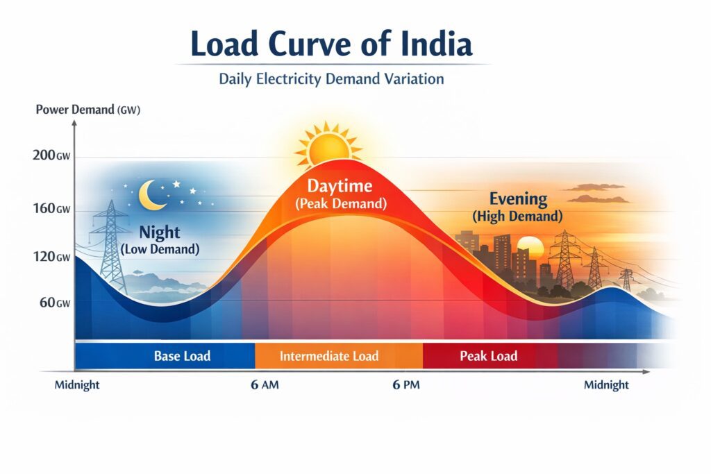
Both statements are correct. A load curve is essential for utility planning and provides important operational insights.
1. Operating Schedule of Generating Units
- Base Load vs. Peak Load: Helps determine which generating units should operate continuously and which should meet peak demand.
- Unit Commitment: Assists in scheduling maintenance and deciding the most economical sequence for starting generators.
2. Total Installed Capacity
- Peak Demand: The highest point on the load curve represents maximum system demand.
- Capacity Planning: Installed capacity must exceed peak demand to maintain reliability and include reserve margin.
Both Statement 1 and Statement 2 are correct.
35. Consider the transfer function G(s) = 10/s, the frequency at which the magnitude of G(s) in bode plot is 0 dB is
(a) For all frequencies < 1 rad/s
(b) For all frequencies < 10 rad/s
(c) 1 rad/s
(d) 10 rad/s
Answer: (d) 10 rad/s
Explanation: In a Bode plot, the magnitude in decibels is given by 20 log of magnitude. For the function 10 divided by s, the magnitude becomes 10 divided by omega. For 0 dB, the magnitude must be 1, which occurs when omega equals 10 rad per second.
36. The open loop transfer function of a unity gain negative feedback control system is given by G(s) = K / [s(s+3)(s+7)]. What is the value of K for which the system damping ratio is 1.0?
(a) 4
(b) 7
(c) 3
(d) 5
Answer: (d) 5
Explanation: A damping ratio of one indicates a critically damped system. Forming the characteristic equation and solving for the value of K that gives critical damping results in K equal to 5.
37. An open loop transfer function of a unity feedback system is given by G(s) = 1 / (s + 2)². The closed loop poles are
(a) –2, –2
(b) –2, –1
(c) –2 + j, –2 – j
(d) –2, 2
Answer: (c) –2 + j, –2 – j
Explanation: The closed loop poles are obtained from the characteristic equation formed by one plus G(s) equals zero. Solving the resulting quadratic equation gives complex conjugate roots, indicating an underdamped response.
38. The transfer function C(s)/R(s) for the signal flow shown in figure is
(a) (G1 + G2) / (1 + H1 + H2)
(b) (G1 + G2) / (1 – H1 + H2)
(c) (G1 + G2) / (1 + G1H1 + G2H2)
(d) (G1 + G2) / (1 – H1 – H2)
Answer: (a) (G1 + G2) / (1 + H1 + H2)
Explanation: Using Mason gain formula, the numerator is obtained from parallel forward paths, giving G1 plus G2. The denominator accounts for feedback loops, and since they are negative feedback loops, the expression simplifies to one plus H1 plus H2.
39. Transfer function for the following bode plot shown in the figure is
(a) 0.1s²
(b) 1.0/s²
(c) 10/s²
(d) 20/s²
Answer: (b) 1.0/s²
Explanation: The slope of minus forty decibels per decade indicates a double pole at origin, corresponding to one divided by s squared. Since the magnitude is zero decibels at one rad per second, the gain is one, giving the transfer function one divided by s squared.
40. The state space equation is given as… The system is
(a) Controllable and observable
(b) Controllable and not observable
(c) Not controllable and observable
(d) Not controllable and not observable
Answer: (a) Controllable and observable
Explanation: A system is controllable if the controllability matrix has full rank, and observable if the observability matrix has full rank. Since both matrices have non-zero determinant, the system is fully controllable and observable.
41 In Force current analogy, the flux of the electrical system is analogous to _______ of the mechanical system
(a) Mass
(b) Velocity
(c) Displacement
(d) Spring Constant
Answer: (c) Displacement
Explanation: In the force current analogy, also known as the inverse analogy, the mechanical force corresponds to current. In this analogy, magnetic flux represents mechanical displacement, while voltage corresponds to velocity.
42 The largest time constant of the characteristic equation (s^2+2s+2)(s+3) = 0 is
(a) 1
(b) 1.5
(c) 2
(d) 3
Answer: (a) 1
Explanation: The roots of the characteristic equation are -3 and -1 plus or minus j1. The time constant is the reciprocal of the real part of the poles. Thus, the time constants are 1 by 3 and 1, and the largest time constant is 1.
43 The eigen values of the matrix A = [0 1 0; 0 0 1; 0 -2 -3] are
(a) 0, –1, –2
(b) 0, –3, –4
(c) 0, 0 , –4
(d) None of these
Answer: (a) 0, –1, –2
Explanation: The eigenvalues are obtained by solving the characteristic equation determinant of lambda I minus A equals zero. This simplifies to lambda cube plus 3 lambda square plus 2 lambda equals zero, which factors as lambda into lambda plus 1 into lambda plus 2, giving eigenvalues 0, minus 1, and minus 2.
44 The dependent source in the circuit shown below is
(a) Voltage-controlled current source
(b) Voltage-controlled voltage source
(c) Current-controlled current source
(d) Current-controlled voltage source
Answer: (d) Current-controlled voltage source
Explanation: A dependent source represented by a diamond symbol with plus and minus signs indicates a voltage source. If its magnitude depends on a current elsewhere in the circuit, it is classified as a current-controlled voltage source.
45 If the voltage across a 5 farad capacitor is 2te–3t V, the current through the capacitor is
(a) 30te–3t A
(b) –30te–3t A
(c) 30te–3t – 10e–3t A
(d) 10e–3t – 30te–3t A
Answer: (d) 10e–3t – 30te–3t A
Explanation: The current through a capacitor is given by i equals C into dv by dt. Differentiating 2te–3t using the product rule gives 2e–3t minus 6te–3t. Multiplying by capacitance 5 farad results in 10e–3t minus 30te–3t ampere.
46 A single phase 2 KVA, 100/200 V transformer is reconnected as an auto transformer such that its KVA rating is maximum. The new rating in KVA is
(a) 2 KVA
(b) 3 KVA
(c) 4 KVA
(d) 6 KVA
Answer: (d) 6 KVA
Explanation: In an auto transformer, the power rating increases due to both conductive and inductive power transfer. The multiplication factor is V high divided by V high minus V low. For this case, the factor is 3, hence the new rating becomes 6 KVA.
47 A 500 KVA transformer has constant losses of 500 W and copper losses at full load is 2000 W. Then at what load is the efficiency maximum?
(a) 125 KVA
(b) 250 KVA
(c) 500 KVA
(d) 1000 KVA
Answer: (b) 250 KVA
Explanation: Maximum efficiency occurs when iron loss equals copper loss. The load factor is square root of iron loss divided by full load copper loss, which is square root of 500 by 2000 equals 0.5. Therefore, maximum efficiency occurs at 50 percent load, which is 250 KVA.
48 A three phase synchronous generator is operating at 0.8 pf lagging with respect to excitation voltage. Nature of armature reaction mmf produced by the armature current is
(a) magnetising
(b) demagnetising
(c) cross-magnetising
(d) partly demagnetising and partly cross magnetising
Answer: (d) partly demagnetising and partly cross magnetising
Explanation: At lagging power factor, the armature flux opposes the main field flux, producing a demagnetising effect. It also distorts the flux distribution, causing a cross magnetising effect, hence it is partly demagnetising and partly cross magnetising.
49 For a 3-phase load balanced condition, each phase has the same value of
(a) Impedance
(b) Resistance
(c) Power Factor
(d) All of these
Answer: (d) All of these
Explanation: A balanced three phase system has equal impedance in all phases, ensuring equal current and voltage distribution. Thus, resistance, impedance, and power factor are same in each phase.
50 The number of parallel paths for simplex lap winding in a dc machine is
(a) 1
(b) 2
(c) Number of poles/2
(d) number of poles
Answer: (d) number of poles
Explanation: In a simplex lap winding, the number of parallel paths is equal to the number of poles. This arrangement is suitable for low voltage and high current applications.
51 A synchronous motor is said to be over excited when it operates at
(a) unity power factor
(b) leading power factor
(c) lagging power factor
(d) zero power factor
Answer: (b) leading power factor
Explanation: A synchronous motor is over excited when the field current is higher than required, causing it to draw leading current from the supply. Hence, it operates at a leading power factor.
52 The synchronous speed of a 50 Hz induction motor having 4 poles is
(a) 1000 rpm
(b) 1200 rpm
(c) 1500 rpm
(d) 3000 rpm
Answer: (c) 1500 rpm
Explanation: The synchronous speed is given by the formula Ns equals 120f divided by P. Substituting f equals 50 Hz and P equals 4, we get Ns equals 1500 rpm.
53 Which of the following motor is used for constant speed applications?
(a) Induction motor
(b) DC series motor
(c) Synchronous motor
(d) Universal motor
Answer: (c) Synchronous motor
Explanation: A synchronous motor runs at constant speed equal to the synchronous speed irrespective of load variations. Hence, it is ideal for constant speed applications.
54 The slip of an induction motor is zero at
(a) starting
(b) full load
(c) no load
(d) synchronous speed
Answer: (d) synchronous speed
Explanation: Slip is defined as the difference between synchronous speed and rotor speed. At synchronous speed, both speeds are equal, hence slip becomes zero.
55 Which of the following losses occur in transformer?
(a) Copper loss
(b) Iron loss
(c) Both (a) and (b)
(d) Mechanical loss
Answer: (c) Both (a) and (b)
Explanation: Transformers have no moving parts, so mechanical losses do not occur. The main losses are copper loss in windings and iron loss in core, hence both are present.
56 The efficiency of a transformer is maximum when
(a) copper loss equals iron loss
(b) copper loss is zero
(c) iron loss is zero
(d) load is zero
Answer: (a) copper loss equals iron loss
Explanation: Maximum efficiency condition occurs when variable copper loss equals constant iron loss. This ensures minimum total losses and hence maximum efficiency.
57 Which device is used to measure power in AC circuits?
(a) Ammeter
(b) Voltmeter
(c) Wattmeter
(d) Energy meter
Answer: (c) Wattmeter
Explanation: A wattmeter measures electrical power in AC circuits by considering both voltage and current along with power factor, thus giving true power.
58 The unit of magnetic flux is
(a) Weber
(b) Tesla
(c) Henry
(d) Ampere
Answer: (a) Weber
Explanation: Magnetic flux is measured in Weber, while Tesla represents flux density and Henry represents inductance.
59 Which of the following is a static device?
(a) Transformer
(b) Motor
(c) Generator
(d) Alternator
Answer: (a) Transformer
Explanation: A transformer has no moving parts, hence it is called a static device, unlike motors and generators which involve mechanical rotation.
60 The frequency of the induced emf in a transformer depends on
(a) number of turns
(b) supply frequency
(c) core material
(d) load current
Answer: (b) supply frequency
Explanation: The frequency of induced emf in a transformer is the same as the supply frequency, as it depends on the alternating magnetic flux produced by the input supply.
61 A metal has strain gauge factor of two. Its nominal resistance is 120 ohms. If it undergoes a strain of 10–5, the value of change of resistance in response to the strain is
(a) 4.8 × 10⁻³ ohm
(b) 3.6 × 10⁻³ ohm
(c) 2.4 × 10⁻³ ohm
(d) 1.2 × 10⁻³ ohm
Answer: (c) 2.4 × 10⁻³ ohm
Explanation: The change in resistance is calculated using the formula change in resistance equals gauge factor into nominal resistance into strain. Substituting the given values 2 into 120 into 10 to the power minus 5 gives 0.0024 ohm, which is 2.4 × 10⁻³ ohm.
62 A d.c. voltmeter has a sensitivity of 1000 ohm per volt. When it measures half full scale in 100 V range, the current through the voltmeter will be
(a) 0.5 mA
(b) 1 mA
(c) 5 mA
(d) 50 mA
Answer: (a) 0.5 mA
Explanation: Sensitivity is defined as ohm per volt, which is the reciprocal of full scale current. A sensitivity of 1000 ohm per volt means full scale current is 1 mA. At half full scale, the current becomes 0.5 mA.
63 A 230 V, 10 A, single phase energy meter makes 90 revolutions in 3 minutes at half load rated voltage and unity pf. If the meter constant is 1800 rev per kWh, then its error at half load will be
(a) 13.04% slow
(b) 13.04% fast
(c) 15% slow
(d) 15% fast
Answer: (a) 13.04% slow
Explanation: At half load, the power is 1.15 kW. Energy consumed in 3 minutes is 0.0575 kWh. Expected revolutions are 103.5, but actual are 90, so the meter under registers, making it 13.04% slow.
64 Wavelength of which material is considered for defining the standard metre
(a) Helium
(b) Xenon
(c) Neon
(d) Krypton
Answer: (d) Krypton
Explanation: The standard metre was historically defined using the wavelength of radiation from Krypton 86. This provided a highly precise and reproducible standard of length.
65 The current flowing through the resistor R=100±0.3% ohm is I=2±4% A. The limiting error in the power dissipation in the resistor R is
(a) 4.3%
(b) 16.9%
(c) 5.6%
(d) 8.3%
Answer: (d) 8.3%
Explanation: The power dissipation in a resistor is given by P = I²R. For error calculation, when quantities are raised to powers, their percentage errors are multiplied by the exponent. Therefore, the error in current becomes 2 × 4% = 8%. The resistance error is 0.3%. Adding both errors, the total limiting error in power is 8% + 0.3% = 8.3%.
66 A 0 to 150 V voltmeter has an error of ±2% of full-scale deflection. What is the range of readings if true voltage is 50 V?
(a) 40 V – 50 V
(b) 47 V – 53 V
(c) 0 V – 53 V
(d) 0 V – 51 V
Answer: (b) 47 V – 53 V
Explanation: The error is ±2% of full scale value, which is ±3 V. Therefore, for a true voltage of 50 V, the reading range becomes 50 ± 3 V, i.e., 47 V to 53 V.
67 The input impedance of CRO is approximately
(a) 0 ohm
(b) 0.1 k ohm
(c) 10 k ohm
(d) 1 M ohm
Answer: (d) 1 M ohm
Explanation: A CRO has very high input impedance, typically around 1 mega ohm, so that it does not load the circuit and ensures accurate signal measurement.
68 Which of the following measurements cannot be made with the help of a frequency counter?
(a) Fundamental frequency of input signal
(b) Frequency components of the input signal at least up to third harmonic
(c) Time interval between two pulses
(d) Pulse width
Answer: (b) Frequency components of the input signal at least up to third harmonic
Explanation: A frequency counter measures frequency, time interval, and pulse width. It cannot analyze harmonic components, which require a spectrum analyzer.
69 A 10 bit A D converter is used to digitise an analog signal in the 0 to 5 V range. The maximum peak to ripple voltage that can be allowed in the D C supply voltage is
(a) nearly 100 mV
(b) nearly 50 mV
(c) nearly 25 mV
(d) nearly 5.0 mV
Answer: (d) nearly 5.0 mV
Explanation: The resolution of a 10 bit converter is 5 divided by 1024, which is approximately 4.88 mV. The ripple voltage must be less than resolution, hence it is about 5 mV.
70 The Latching current of SCR is 18 mA. Its holding current will be
(a) 10 mA
(b) 18 mA
(c) 25 mA
(d) 36 mA
Answer: (a) 10 mA
Explanation: In an SCR, the holding current is always less than the latching current. Typically, it is about one half to one third of the latching current. Hence, 10 mA is appropriate.
71 A single-phase half-wave controlled rectifier has 400sin(314t) as the input voltage and R as the load. For the firing angle of 60 deg for the SCR, the average output voltage is
(a) 400/π
(b) 300/π
(c) 240/π
(d) 200/π
Answer: (b) 300/π
Explanation: The average output voltage for a half-wave controlled rectifier is given by Vavg = (Vm / 2π) × (1 + cos α). Here Vm = 400 and α = 60 degrees, so cos 60 degrees = 0.5 and (1 + cos α) = 1.5. Substituting gives (400 × 1.5) / 2π = 300/π.
72 The turn-on time of a SCR with inductive load is 20 micro seconds. The pulse train is 2.5 kHz with a mark/space ratio of 1/10, then the SCR will
(a) turn on
(b) not turn on
(c) turn on if inductance is removed
(d) turn on if pulse frequency is increased to four times
Answer: (a) turn on
Explanation: The time period of the pulse is 1 / 2.5 kHz = 400 microseconds. With a mark space ratio of 1:10, the pulse width is about 36.36 microseconds. Since this is greater than the turn-on time of 20 microseconds, the SCR will turn on successfully.
73 In an inverter with fundamental output frequency of 50 Hz, if third harmonic is eliminated, then frequencies in Hz of other components in the output voltage would be
(a) 250, 350, 500, high frequencies
(b) 250, 350, 550, high frequencies
(c) 50, 100, 350, 550
(d) none of these
Answer: (b) 250, 350, 550, high frequencies
Explanation: A square wave inverter produces odd harmonics such as 3rd, 5th, 7th, 11th. For 50 Hz fundamental, these are 150, 250, 350, 550 Hz. If the third harmonic 150 Hz is eliminated, the remaining components are 250 Hz, 350 Hz and 550 Hz.
74 In the single-phase voltage controller circuit shown in figure below, for what range of triggering angle (α), the output voltage (Vo) is not controllable?
(a) 0 < α < 45°
(b) 45 < α < 135°
(c) 90 < α < 180°
(d) 135 < α < 180°
Answer: (a) 0 < α < 45°
Explanation: In a voltage controller with inductive load, if the triggering angle α is less than the load angle φ, the previous SCR continues conduction. This causes overlapping conduction and the circuit behaves like an uncontrolled rectifier, making the output uncontrollable.
75 In a diode, the reverse recovery time is defined as the time between the instant diode current becomes zero and the instant reverse recovery current decays to
(a) zero
(b) 50% of reverse peak current IRM
(c) 25% of reverse peak current IRM
(d) 10% of reverse peak current IRM
Answer: (c) 25% of reverse peak current IRM
Explanation: Reverse recovery time is defined as the time taken for the reverse current to fall from its peak value to 25 percent of IRM. This parameter is important for switching performance of diodes.
76 A single-phase, half-bridge inverter has an input voltage of 48 V DC. Inverter is feeding a load of 2.4Ω. The r.m.s. output voltage at fundamental frequency is,
(a) 96/π V
(b) 96/(π√2) V
(c) 48/π V
(d) 48/(π√2) V
Answer: (b) 96/(π√2) V
Explanation: The fundamental component of output voltage has peak value 2Vs/π. With Vs = 48 V, peak becomes 96/π. The RMS value is obtained by dividing by √2, giving 96/(π√2).
77 Which one of the following statements express the thermal resistance between the body of a power-semiconductor device and the ambient?
(a) Voltage across the device divided by current through the device.
(b) Temperature difference between body and ambient divided by average power dissipated in the device.
(c) Average power dissipated in the device divided by the square of the rms current in the device
(d) Average power dissipated in the device divided by the temperature difference between body and ambient
Answer: (b) Temperature difference between body and ambient divided by average power dissipated in the device.
Explanation: Thermal resistance is defined as temperature rise divided by power dissipation. It represents how effectively heat flows from the device body to ambient.
78 A DC-DC boost converter, as shown in the figure below, is used to boost 360 V to 400V at a power of 4 kW. All devices are ideal. Considering continuous inductor current, the rms current in the solid state switch (Q), is
(a) 3.16 A
(b) 3.5 A
(c) 5 A
(d) 6.32 A
Answer: (b) 3.5 A
Explanation: The duty cycle is D = 1 − (Vin/Vout) = 0.1. Output current is 4000/400 = 10 A, so input current is 11.11 A. The RMS switch current is I × √D, giving approximately 3.5 A.
79 A MOSFET rated for 15 A, carries a periodic current as shown in figure. The ON state resistance of the MOSFET is 0.15 Ω. The average ON state loss in the MOSFET is
(a) 33.8 W
(b) 15 W
(c) 7.5 W
(d) 3.8 W
Answer: (c) 7.5 W
Explanation: The power loss is calculated using P = Irms² × R. For a 10 A square wave with 50 percent duty cycle, Irms = 7.07 A. Substituting gives (7.07)² × 0.15 ≈ 7.5 W.
80 If A and B are two square matrices such that AB = –BA, then (A + B)² is :
(a) 0
(b) A² + B² + 2AB
(c) A + B
(d) A² + B²
Answer: (d) A² + B²
Explanation: Expanding (A + B)² gives A² + AB + BA + B². Since AB = −BA, the terms AB and BA cancel each other, leaving A² + B².
81 Which option replaces the question mark?
1.
2.
3.
4.
Answer: (d) 4
Explanation: The relationship in the first pair shows that an oar is used to move a canoe. Similarly, a wheel is used to move a car. Hence, the correct answer is car, which corresponds to option 4.
82 Find the replica image to the first
(a) A
(b) B
(c) C
(d) D
Answer: (b) B
Explanation: The correct replica is obtained by rotating the original figure without changing the relative positions of dots and vertices. Only option B maintains the same spatial arrangement, hence it is correct.
83 Which option replaces the question mark?
(a) A
(b) B
(c) C
(d) D
Answer: (b) B
Explanation: The pattern follows a set of transformation rules such as shifting, mirroring, or changing orientation. Applying the same rule step by step leads to the figure in option B.
84 The average life expectancy for the entire United States (US) population is 73.9 years, born in Hawaii will live an average of 77 years, and those born in Louisiana, 71.7 years. If a newlywed couple from Louisiana were to begin their family in Hawaii, therefore, their children would be expected to live longer than would be the case if the family remained in Louisiana. Which of the following, if true, would most seriously weaken the conclusion drawn in the passage?
(a) Insurance company statisticians do not believe that moving to Hawaii will significantly lengthen the average Louisianan’s life.
(b) The governor of Louisiana has falsely alleged that statistics for his state are inaccurate
(c) The longevity ascribed to Hawaii’s current population is attributable mostly to genetically determined factors
(d) Thirty percent of all Louisianans can expect to live longer than 77 years
Answer: (c) The longevity ascribed to Hawaii’s current population is attributable mostly to genetically determined factors
Explanation: The conclusion assumes that location causes longer life. If longevity is due to genetic factors, then simply moving to Hawaii will not increase lifespan. This breaks the cause-effect link, weakening the argument.
85 Choose one of the following options that means the opposite of the given word: AWARE
(a) Uncertain
(b) Ignorant
(c) Sure
(d) Doubtful
Answer: (b) Ignorant
Explanation: The word aware means having knowledge or understanding. The opposite is ignorant, which means lack of knowledge or awareness.
86 Six people P, Q, R, S, T and U are sitting on the ground in a hexagonal shape. 1. All the sides of the hexagon, so formed are of same length. 2. P is not adjacent to Q or R. 3. S is not adjacent to R or T. 4. Q and R are adjacent. 5. U is in the middle of S and R. Who is at the same distance from S as T is from S?
(a) Q
(b) S
(c) R
(d) U
Answer: (a) Q
Explanation: Arranging the people based on the given conditions gives a symmetrical hexagon. In this arrangement, both Q and T are at the same distance from S, so the correct answer is Q.
87 Which one will replace the question mark?
(a) 42
(b) 12
(c) 44
(d) 11
Answer: (d) 11
Explanation: The pattern involves calculating the difference between sums of opposite numbers. Applying the same logic to the final set gives the value 11.
88 Which one will replace the question mark?
(a) 78
(b) 64
(c) 75
(d) 84
Answer: (b) 64
Explanation: The sequence follows the pattern of cubes of natural numbers such as 1³, 2³, 3³. The next value is 4³ = 64.
89 Which one replaces the question mark?
(a) A
(b) B
(c) C
(d) D
Answer: (a) A
Explanation: Each symbol represents a specific transformation rule. Applying the correct sequence of operations gives the result matching option A.
90 Fact 1: Islands are surrounded by water. Fact 2: Maui is an island. Fact 3: Maui was formed by a volcano. If the first three statements are facts, which of the following statements must also be a fact? I : Maui is surrounded by water. II: All islands are formed by volcanoes. III: All volcanoes are on islands.
(a) I only
(b) II only
(c) III only
(d) None of the statements is a known fact
Answer: (a) I only
Explanation: From the given facts, since Maui is an island and all islands are surrounded by water, it follows that Maui is surrounded by water. The other statements are not logically supported by the given facts.
91 The theory of relativity, developed by Albert Einstein, revolutionized the field of physics. It challenged the traditional Newtonian concepts of time, space, and gravity. Einstein’s theory proposed that time and space are not absolute but are interconnected dimensions that form a four-dimensional fabric called space time. It also introduced the concept of gravity as the curvature of space time caused by the presence of mass and energy. What was the impact of Albert Einstein’s theory of relativity?
(a) It presented a new model of space time and revolutionized the understanding of time, space, and gravity
(b) It disproved the traditional Newtonian concepts and established the absolute nature of time and space
(c) It focused on the interplay between mass and energy but did not significantly impact the field of physics
(d) It introduced the concept of space time but had minimal influence on the understanding of gravity
Answer: (a) It presented a new model of space time and revolutionized the understanding of time, space, and gravity
Explanation: The theory of relativity replaced the idea of absolute time and space with a unified concept of space time. It redefined gravity as the curvature of space time caused by mass and energy, thus revolutionizing physics.
92 B2CD, _____, BCD4, B5CD, BC6D
(a) B2C2D
(b) BC3D
(c) B2C3D
(d) BCD7
Answer: (b) BC3D
Explanation: The pattern shows a number increasing sequentially from 2 to 6 while shifting its position within the string BCD. After B2CD, the number moves to the next position forming BC3D, followed by BCD4, and so on.
93 Study the table carefully and answer the question given below Which company has the highest actual production of cars over these years?
(a) A
(b) B
(c) C
(d) D
Answer: (c) C
Explanation: By adding the actual production values, Company C has the highest total production compared to all other companies, making it the correct answer.
94 Study the table carefully and answer the questions given below In which bank was the disbursement of loans more than 25 percent of all banks in 1986?
(a) I
(b) II
(c) III
(d) IV
Answer: (a) I
Explanation: The total disbursement is calculated first, and 25 percent of this total is determined. Only Bank I has a value greater than this threshold, so it is correct.
95 Find the point c in the curve f(x) = x³ + x² + x + 1 in the interval where slope of a tangent to a curve is equals to the slope of a line joining (0,1)
(a) 0.64
(b) 0.54
(c) 0.44
(d) 0.34
Answer: (b) 0.54
Explanation: Using the Mean Value Theorem, the slope of the secant line between the points is calculated and equated to the derivative of the function. Solving the resulting equation gives the value of c approximately equal to 0.54.