Motor Current Signature Analysis (MCSA) is a diagnostic techniques for detecting faults in electric motors and their driven equipment. By analyzing the current drawn by a motor during operation, we can identify developing problems before they lead to actual failures, enabling the transition from reactive to predictive maintenance strategies.
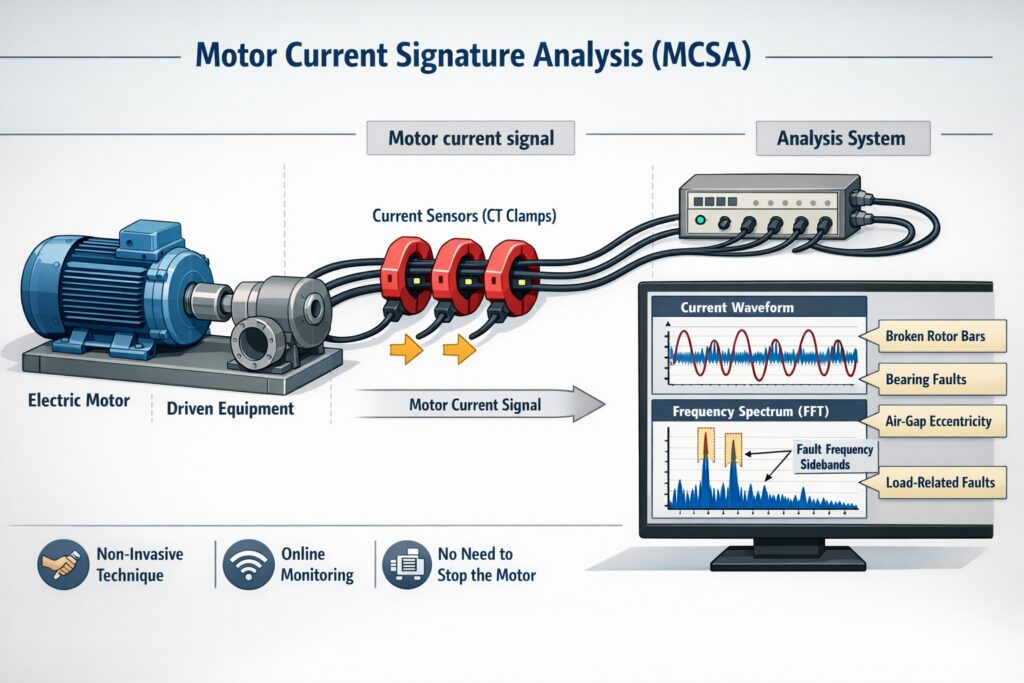
Unlike traditional vibration analysis or thermal imaging, MCSA requires no direct contact with the motor and can be performed while the equipment remains in service. This technique leverages the fundamental principle that motor current contains a wealth of information about the motor’s mechanical and electrical condition, as well as the health of the driven load.
Any fault in a motor changes the air-gap magnetic field. This modulates stator current leading to fault-specific frequency components appear in the current spectrum.
Table of Contents
Fundamental Principles of MCSA
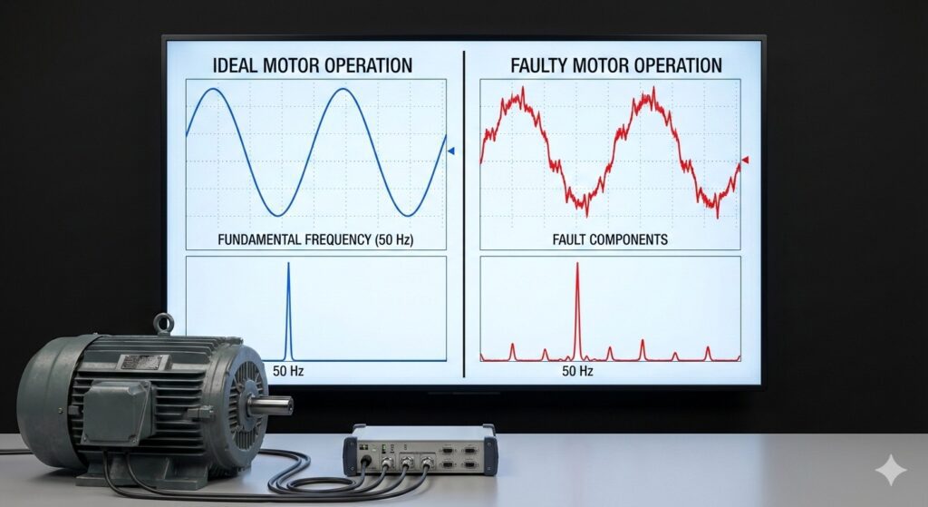
Electric motors, particularly three-phase induction motors which dominate industrial applications, draw current in patterns that reflect their operational state. When a motor operates under ideal conditions, its current signature exhibits a clean fundamental frequency corresponding to the supply frequency (typically 50 Hz or 60 Hz depending on the region). However, mechanical or electrical faults introduce additional frequency components into the current signal.
The relationship between mechanical faults and electrical signatures stems from the interaction between the motor’s magnetic field and its rotating components. When a rotor bar cracks, a bearing degrades, or shaft misalignment occurs, these mechanical anomalies modulate the airgap flux, which in turn modulates the stator current. By applying Fast Fourier Transform (FFT) analysis to the current waveform, these modulations appear as discrete frequency components that can be identified and analyzed.
How Motors Create Current Signatures?
When a three-phase induction motor operates in perfect health, here’s what happens electrically:
The Supply Creates a Rotating Magnetic Field
Three-phase AC power (at 50 Hz or 60 Hz) flows into the stator windings. These three phases are offset by 120 degrees from each other. When combined, they create a smoothly rotating magnetic field inside the motor. Think of it like three people pushing a merry-go-round at evenly spaced intervals—the result is smooth, continuous rotation.
The Rotor Follows the Magnetic Field
This rotating magnetic field induces currents in the rotor bars (in a squirrel cage motor). These induced currents create their own magnetic field, which interacts with the stator’s field. The rotor “chases” the rotating field but never quite catches it—this difference is called “slip.”
The Current Signature is Clean
In this ideal state, if you measure the current flowing into the motor and plot its frequency spectrum (using Fast Fourier Transform), you’d see:
- A dominant peak at the supply frequency (50 Hz or 60 Hz)—this is called the fundamental frequency
- Very small harmonics at integer multiples (100/120 Hz, 150/180 Hz, etc.) due to minor imperfections
- A relatively “quiet” spectrum with minimal additional frequency components
This is your baseline—the signature of health.
Key Frequency Components
The most important frequencies examined in MCSA include:
Supply Frequency (fs): The fundamental frequency of the electrical supply, which serves as the reference point for all other frequencies.
Slip Frequency (fslip): The difference between synchronous speed and actual rotor speed, calculated as fslip = fs × slip, where slip is typically 1-5% for healthy induction motors.
Pole Pass Frequency (fp): Related to the number of poles and rotational speed, calculated as fp = (number of poles/2) × rotational frequency.
Bearing Frequencies: Specific frequencies related to bearing geometry, including Ball Pass Frequency Outer Race (BPFO), Ball Pass Frequency Inner Race (BPFI), Fundamental Train Frequency (FTF), and Ball Spin Frequency (BSF).
Types of Faults Detected by MCSA
Rotor Bar and End Ring Faults
Broken or cracked rotor bars represent one of the most common failures in squirrel cage induction motors, particularly in applications with frequent starts, high inertia loads, or thermal cycling. When a rotor bar breaks, it creates an asymmetry in the rotor’s magnetic field, producing torque pulsations at slip frequency.
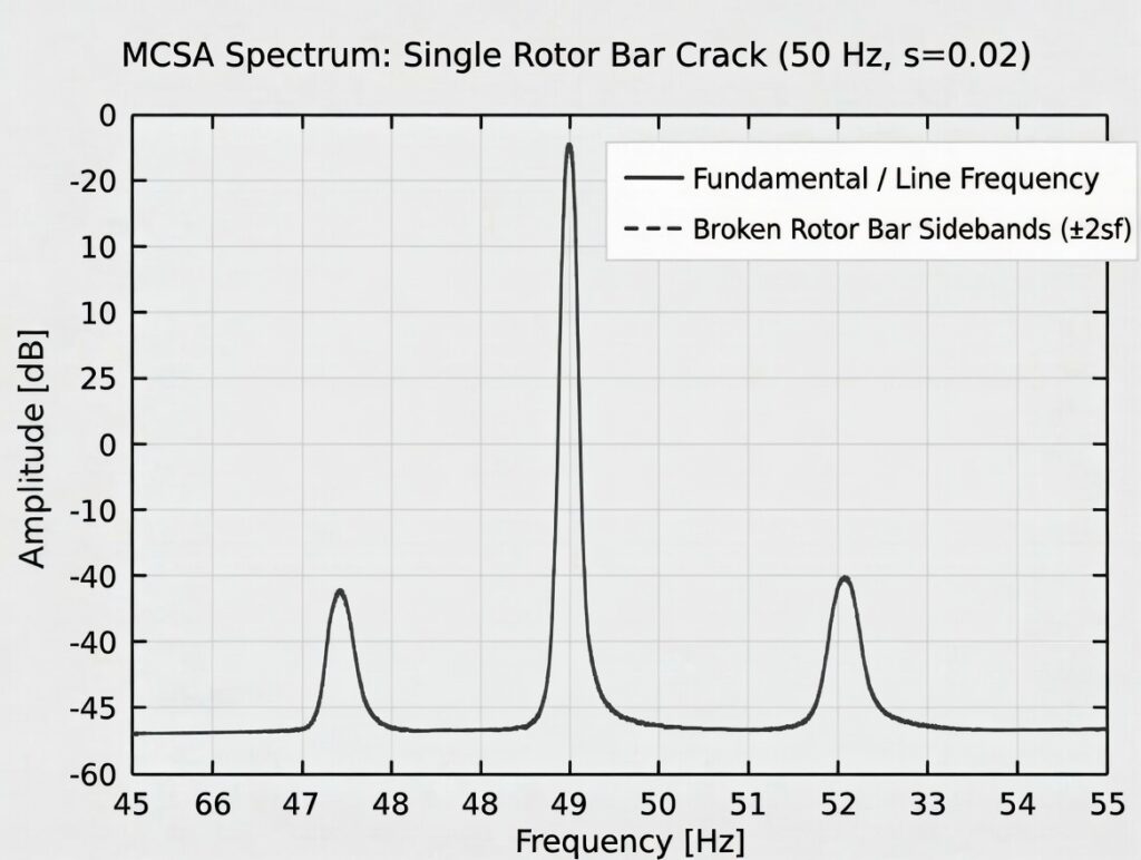
These pulsations manifest in the current spectrum as sidebands around the supply frequency, specifically at:
f_brb = fs × (1 ± 2ks)
where k = 1, 2, 3… and s is the slip.
The amplitude of these sidebands increases as the fault severity progresses. In early stages, the sidebands may be only 40-50 dB below the fundamental frequency, but as multiple bars break, the amplitude difference can decrease to 20-30 dB, indicating severe damage.
Bearing Faults
Bearing failures account for approximately 40-50% of all motor failures in industrial applications. MCSA detects bearing faults by identifying characteristic frequencies that appear when rolling elements interact with defects on the inner race, outer race, or balls themselves.
The bearing fault frequencies appear as sidebands around the supply frequency and can be calculated using bearing geometry:
BPFO = (n/2) × fr × (1 – (Bd/Pd) × cos φ)
BPFI = (n/2) × fr × (1 + (Bd/Pd) × cos φ)
BSF = (Pd/2Bd) × fr × [1 – (Bd/Pd)² × cos² φ]
FTF = (fr/2) × (1 – (Bd/Pd) × cos φ)
where n is the number of rolling elements, fr is the rotational frequency, Bd is the ball diameter, Pd is the pitch diameter, and φ is the contact angle.
Early-stage bearing faults produce very small current modulations, often requiring advanced signal processing techniques such as envelope analysis or wavelet transforms to detect.
Stator Winding Faults
Stator winding faults, including turn-to-turn shorts, phase-to-phase faults, and ground faults, create an imbalance in the three-phase system. This imbalance produces a negative sequence current component and introduces specific frequency signatures.
Inter-turn short circuits create harmonics at frequencies related to the supply frequency and can be detected by monitoring the third harmonic content. A healthy motor typically shows third harmonic levels below 1% of the fundamental, while motors with developing stator faults may exhibit levels exceeding 3-5%.
Air Gap Eccentricity
Air gap eccentricity occurs when the rotor is not perfectly centered within the stator bore. This condition can be static (rotor center offset from stator center but rotating on its true axis) or dynamic (rotor rotating about an axis that doesn’t coincide with its geometric center).
Eccentricity produces sidebands around the principal slot harmonics at frequencies:
f_ecc = fs × [1 ± k(1-s)/p]
where p is the number of pole pairs and k = 1, 2, 3…
Severe eccentricity can lead to unbalanced magnetic pull, accelerated bearing wear, and eventual catastrophic failure.
Load-Related Issues
MCSA can also identify problems in the driven equipment, such as misalignment, unbalance, looseness, and pump cavitation. These mechanical issues in the load create torque variations that modulate the motor current at characteristic frequencies related to the shaft rotational speed and the specific fault mechanism.
MCSA Implementation Methodology
Data Acquisition
Successful MCSA requires high-quality current measurements with adequate sampling rates and resolution. Current transducers such as Hall effect sensors, Rogowski coils, or current transformers capture the three-phase currents. The sampling frequency must satisfy the Nyquist criterion, typically requiring sampling rates of at least 5-10 kHz for general fault detection, though bearing fault analysis may require rates up to 20 kHz or higher.
Data should be collected under steady-state operating conditions whenever possible, as transient events and load variations can introduce artifacts into the frequency spectrum. Recording periods of 10-60 seconds typically provide sufficient data for robust FFT analysis with adequate frequency resolution.
Signal Processing
The raw current data undergoes several processing steps:
Filtering: Anti-aliasing filters prevent high-frequency noise from corrupting the analysis. Bandpass filters may isolate specific frequency ranges of interest.
Windowing: Applying window functions (Hanning, Hamming, Blackman) to the time-domain data reduces spectral leakage in the FFT.
FFT Analysis: Transforms the time-domain current signal into the frequency domain, revealing the amplitude and phase of each frequency component.
Envelope Analysis: For bearing fault detection, demodulating the current signal and analyzing the envelope can enhance the visibility of low-amplitude bearing fault signatures.
Trend Analysis: Comparing current spectra over time reveals the progression of faults, enabling predictive maintenance scheduling.
Diagnostic Criteria
Establishing baseline signatures for motors in healthy condition provides reference points for fault detection. Diagnostic thresholds vary by motor size, application, and criticality, but general guidelines include:
- Rotor bar fault sidebands exceeding -45 dB relative to the fundamental indicate developing problems
- Bearing fault frequencies with amplitudes above -60 dB warrant investigation
- Third harmonic content above 3% suggests stator winding issues
- Eccentricity sidebands greater than -50 dB indicate significant air gap problems
Advanced diagnostic systems employ machine learning algorithms trained on historical data to automatically classify fault types and severity levels.
Practical Industrial Examples
Example 1: Pulp and Paper Mill – Refiner Motor Failure Prevention
A Canadian pulp and paper mill implemented MCSA on their critical refiner motors, which process wood chips into pulp. These 3 MW motors operate under severe mechanical stress with variable loads and frequent thermal cycling.
Challenge: The mill experienced unexpected refiner motor failures approximately every 18-24 months, resulting in production losses exceeding $50,000 per incident and emergency repair costs of $30,000-$40,000.
Implementation: MCSA monitoring was installed on six refiner motors, with continuous current monitoring and weekly automated spectral analysis. The system tracked rotor bar fault frequencies, bearing fault signatures, and load-related anomalies.
Results: Within three months, the system detected developing rotor bar faults in one motor, evidenced by sidebands at fs(1±2s) with amplitudes at -38 dB. The motor was scheduled for rebuild during the next planned maintenance outage rather than failing catastrophically. Over two years, the system identified four developing faults, enabling planned interventions that:
- Eliminated unplanned downtime related to refiner motor failures
- Reduced repair costs by 45% through planned maintenance vs. emergency repairs
- Extended average motor life from 18 months to 36+ months through early intervention
- Provided an ROI of 340% in the first two years
Example 2: Water Treatment Facility – Pump Motor Bearing Failure
A municipal water treatment plant in Texas monitored 45 pump motors ranging from 50 HP to 500 HP using periodic MCSA testing conducted quarterly.
Challenge: Bearing failures in the pump motors caused service interruptions and required emergency repairs. The facility used vibration analysis but wanted additional diagnostic capability without installing permanent sensors on all motors.
Implementation: Maintenance technicians performed quarterly MCSA testing using portable equipment, collecting 30-second current samples from each motor under normal operating conditions. The data was analyzed for bearing fault frequencies specific to each motor’s bearing type.
Results: During a routine quarterly test, MCSA detected elevated bearing fault frequencies on a 200 HP pump motor serving a critical treatment process. The BPFO signature appeared at -54 dB, suggesting early-stage outer race degradation. Vibration analysis at the time showed no abnormal indicators. The facility scheduled bearing replacement for the next monthly maintenance window, four weeks later.
When the motor was disassembled, the outer race showed initial spalling across approximately 15% of its surface. Had the motor run to failure, it would have caused damage to the pump shaft and impeller, increasing repair costs from $3,500 for bearing replacement to an estimated $18,000 for complete pump rebuild, plus 3-5 days of downtime for a critical process.
Example 3: Steel Manufacturing – Rolling Mill Motor Rotor Bars
A steel manufacturing facility in Germany operates massive rolling mill motors (6 MW) that experience extreme cyclical loading during steel slab processing. These motors accelerate and decelerate repeatedly, subjecting rotor bars to severe thermal and mechanical stress.
Challenge: Rotor bar failures occurred without warning, causing mill shutdowns lasting 4-7 days for motor rebuild or replacement. Each incident cost approximately €200,000 in lost production plus €80,000-€120,000 in repair costs.
Implementation: The facility installed permanent MCSA monitoring on all four rolling mill motors, with continuous data acquisition and automated analysis algorithms running every hour. The system tracked rotor bar fault sidebands and generated alerts when amplitudes crossed predefined thresholds.
Results: Eight months after installation, the system detected increasing rotor bar fault signatures in Motor #3. Initial detection showed sidebands at -47 dB. Over the following six weeks, technicians tracked progression to -42 dB, then -38 dB, confirming multiple rotor bars had fractured.
The facility coordinated a planned shutdown during a period of reduced steel demand, rebuilding the motor rotor during a scheduled 5-day maintenance window. Post-rebuild analysis revealed seven broken rotor bars and extensive end ring damage. The predictive approach enabled:
- Coordination with production scheduling to minimize revenue impact
- Procurement of materials and specialized labor in advance
- Completion of repairs within the planned window without extension
- Estimated savings of €280,000 compared to an unplanned failure scenario
- Prevention of potential secondary damage to the gearbox and mill stand
Example 4: Mining Operation – Conveyor Motor Misalignment Detection
An Australian iron ore mining operation uses hundreds of conveyor motors to transport material across several kilometers. These motors operate continuously in harsh environmental conditions with heavy dust and vibration.
Challenge: Misalignment between motors and conveyor drives caused premature bearing failures, belt tracking issues, and reduced equipment life. Traditional alignment methods were applied during installation, but operating conditions caused alignment to drift over time.
Implementation: The mine implemented periodic MCSA testing on critical conveyor motors during monthly preventive maintenance inspections. Technicians analyzed the current spectra for load-related frequencies indicating misalignment, specifically sidebands at 1× and 2× rotational frequency.
Results: Testing identified misalignment signatures on 12 motors over six months. In one case, a 75 kW conveyor motor showed significant 1× and 2× rotational frequency components at -35 dB and -42 dB respectively, indicating moderate misalignment.
Precision alignment procedures corrected the angular and offset misalignment. Follow-up MCSA testing confirmed the alignment signatures decreased to below -55 dB. The intervention prevented premature bearing failure (predicted within 2-3 months based on wear trends) and extended bearing life by an estimated 18 months. Across all identified cases, the alignment corrections delivered:
- 65% reduction in bearing replacement frequency for corrected motors
- Decreased energy consumption averaging 3-4% per motor due to reduced friction
- Annual savings of approximately $185,000 in parts and labor
- Improved conveyor reliability reducing production interruptions
Example 5: Chemical Processing – Compressor Motor Stator Fault
A petrochemical plant in the Netherlands operates critical compressor motors supporting continuous process operations. A 2 MW motor driving a refrigeration compressor showed unusual thermal patterns during infrared thermography surveys.
Challenge: The thermal signature suggested possible stator winding issues, but confirming the fault required diagnostic verification before committing to an expensive motor rewind or replacement.
Implementation: The plant’s reliability team performed detailed MCSA testing, focusing on harmonic content and phase imbalance indicators. They collected current data from all three phases simultaneously and analyzed the harmonic spectrum and negative sequence components.
Results: MCSA revealed elevated third harmonic content at 4.2% of fundamental frequency and significant negative sequence current at 8.3% of positive sequence. These indicators strongly suggested inter-turn short circuits in the stator winding. Phase-to-phase comparison showed asymmetry consistent with Phase A winding degradation.
The motor was removed from service during a planned process shutdown two weeks later. Detailed electrical testing confirmed a turn-to-turn fault in Phase A, involving approximately 6% of the winding. The motor underwent complete rewind rather than catastrophic failure, which would have caused:
- Emergency shutdown of the refrigeration system affecting multiple process units
- Potential loss of temperature control leading to off-spec product (estimated value €400,000)
- Extended downtime of 3-4 weeks vs. the planned 10-day turnaround
- Environmental release risk from refrigerant system overpressure
- Estimated total avoidance value of €850,000
Example 6: Food and Beverage – Mixer Motor Load Analysis
A large bakery operation in the United States uses industrial mixers with 25 HP motors operating on varying duty cycles depending on dough type and batch size.
Challenge: Operators noticed inconsistent mixing quality and suspected mechanical issues in the mixing paddles or gearbox, but visual inspection showed no obvious problems.
Implementation: The maintenance team applied MCSA to analyze the load signature during different mixing cycles, comparing current patterns between mixers and across different product recipes.
Results: Analysis revealed that one mixer drew 15-20% higher current during specific portions of the mixing cycle compared to identical units processing the same recipes. The current variations occurred at frequencies corresponding to the paddle rotational speed, suggesting mechanical resistance.
Upon disassembly, technicians discovered that product buildup on the paddle shaft had created interference with the mixer bowl, increasing mechanical friction. Additionally, a worn gearbox bearing created additional drag at specific rotational positions. Cleaning the buildup and replacing the bearing resolved the issues, resulting in:
- Normalized current consumption matching other identical mixers
- Improved batch consistency and product quality
- 8% reduction in energy consumption for that mixer
- Prevention of potential paddle shaft damage from continued interference
- Identification of a cleaning protocol modification to prevent recurrence
Advanced MCSA Techniques
Transient MCSA
While traditional MCSA analyzes steady-state current signatures, transient MCSA examines current during motor starting and stopping sequences. During startup, the high current and electromagnetic forces can reveal faults that produce minimal signatures during steady-state operation. This technique proves particularly valuable for detecting rotor bar faults, as the thermal and electromagnetic stresses during starting accentuate the broken bar effects.
Artificial Intelligence and Machine Learning Integration
Modern MCSA systems increasingly incorporate AI and machine learning algorithms to enhance diagnostic accuracy and reduce false positives. These systems learn normal operational patterns for each motor, accounting for load variations, ambient temperature effects, and seasonal changes. Anomaly detection algorithms flag deviations from established baselines, while classification models trained on historical failure data predict fault types and severity with increasing accuracy.
Neural networks can process the entire current spectrum simultaneously, identifying subtle patterns that human analysts might overlook. Some advanced systems achieve fault classification accuracy exceeding 95% for common fault types in controlled industrial environments.
Wireless and IoT-Enabled MCSA
The integration of MCSA with Industrial Internet of Things (IIoT) platforms enables continuous monitoring of distributed motor populations without extensive wiring infrastructure. Wireless current sensors communicate with cloud-based analytics platforms, providing real-time dashboards accessible from anywhere. These systems aggregate data from hundreds or thousands of motors, applying fleet-level analytics to identify trends, benchmark performance, and optimize maintenance strategies across entire facilities or enterprise-wide operations.
Advantages and Limitations of MCSA
Advantages
Non-invasive Testing: MCSA requires no physical contact with rotating components, eliminating safety concerns and enabling testing on operating equipment.
Comprehensive Fault Coverage: A single diagnostic technique detects electrical, mechanical, and load-related faults across multiple failure modes.
Remote Monitoring Capability: Current signals can be measured at motor control centers or distribution panels, enabling monitoring of inaccessible or hazardous locations.
Cost-Effective Implementation: Compared to permanent vibration monitoring installations, MCSA equipment costs significantly less, particularly for portable testing applications.
Early Fault Detection: Many fault types produce current signature changes before vibration or thermal symptoms become apparent.
Load Condition Insight: MCSA provides information about driven equipment performance, enabling process optimization beyond fault detection.
Limitations
Skill Requirements: Accurate interpretation of current spectra requires trained analysts who understand motor theory, signal processing, and application-specific operating conditions.
Load Variation Sensitivity: Fluctuating loads introduce spectral components that can mask fault signatures or create false indications, particularly in applications with highly variable processes.
Small Motor Challenges: Motors below 5 HP may produce insufficient current modulation for reliable fault detection using standard techniques, though enhanced signal processing methods are improving capabilities in this range.
Bearing Fault Detection Limitations: Early-stage bearing faults produce very small current modulations that may not exceed noise floors without advanced processing techniques. MCSA typically detects bearing faults later than specialized vibration analysis methods.
Environmental Noise: Electrical noise from variable frequency drives, power quality issues, or adjacent equipment can contaminate current signals, requiring filtering and signal conditioning.
Specificity Limitations: While MCSA effectively identifies that a fault exists, pinpointing the exact location (which specific bearing, which phase winding) may require supplementary diagnostic techniques.
Integration with Comprehensive Maintenance Programs
MCSA delivers maximum value when integrated into a comprehensive predictive maintenance program alongside complementary technologies. Vibration analysis provides superior sensitivity for early bearing fault detection and mechanical imbalance. Thermal imaging identifies hot spots and electrical connection problems. Oil analysis monitors lubricant condition and wear particle generation. Ultrasonic testing detects electrical tracking and compressed air leaks.
The most sophisticated reliability programs employ a multi-technology approach, where MCSA serves as a primary screening tool for electrical and rotating equipment, with confirmatory testing using task-specific methods when MCSA identifies potential issues. This layered diagnostic strategy optimizes the balance between monitoring costs and diagnostic confidence.
Modern computerized maintenance management systems (CMMS) integrate data from multiple diagnostic technologies, creating comprehensive equipment health records that support data-driven maintenance decisions, spare parts optimization, and long-term asset management strategies.
Future Trends in MCSA
The evolution of MCSA technology continues to expand its capabilities and applications. Digital twin technology enables simulation of motor behavior under various fault conditions, improving diagnostic algorithm training and fault severity prediction. Edge computing platforms process current signals locally at the motor control center, reducing data transmission requirements while enabling real-time fault detection with millisecond response times.
Advanced sensor fusion combines current signatures with voltage, temperature, vibration, and acoustic data in unified diagnostic models, leveraging the complementary strengths of each technology. Blockchain-based maintenance records create immutable audit trails for critical equipment, supporting regulatory compliance and warranty claims.
The integration of MCSA with augmented reality maintenance support systems guides technicians through diagnostic procedures and repair processes, displaying real-time current signatures and diagnostic recommendations overlaid on the physical equipment through smart glasses or mobile devices.
Conclusion
Motor Current Signature Analysis has matured from a specialized research technique into a mainstream predictive maintenance tool deployed across diverse industries worldwide. Its ability to detect multiple fault types non-invasively, combined with decreasing equipment costs and advancing analytical capabilities, makes MCSA an essential component of modern reliability programs.
The industrial examples presented demonstrate MCSA’s practical value in preventing catastrophic failures, enabling planned interventions, and optimizing maintenance resources. From pulp mills to steel plants, water treatment facilities to chemical processing operations, MCSA delivers measurable returns through reduced downtime, extended equipment life, and improved operational safety.
Success with MCSA requires more than just purchasing equipment. Organizations must invest in personnel training, establish robust diagnostic protocols, maintain comprehensive baseline databases, and integrate MCSA data with broader maintenance decision-making processes. When implemented thoughtfully as part of a comprehensive reliability strategy, MCSA transforms maintenance from reactive firefighting to proactive asset management, delivering sustainable competitive advantages in industries where equipment reliability directly impacts profitability and operational excellence.
As technology continues advancing, MCSA will become increasingly automated, accessible, and integrated into intelligent maintenance ecosystems that predict failures before they occur, optimize equipment performance continuously, and enable the transition to truly predictive and prescriptive maintenance strategies. Organizations that embrace these capabilities today position themselves for leadership in the reliability-centered manufacturing environments of tomorrow.