The Short Circuit Test is conducted on a synchronous machine to determine the relationship between field current ($I_f$) and armature current ($I_{sc}$) under short-circuit conditions.
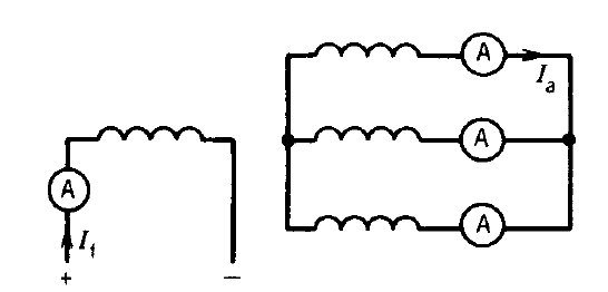
Table of Contents
Purpose of Short Circuit Test
- To obtain the Short Circuit Characteristic (SCC)
- To determine:
- Armature current under short circuit
- Synchronous reactance (Xₛ) (with OCC)
- Used for performance and fault analysis
Test Principle
The machine is run at rated speed, and the armature terminals are short-circuited, while the field current is varied.
Test Setup
- Machine driven at rated speed by a prime mover
- Stator terminals are short-circuited (through ammeters)
- Field winding supplied with DC current
- Ammeter measures armature current
Step-by-Step Procedure
- Start the machine and bring it to rated speed
- Connect all three stator terminals together
- Use ammeters to measure current
- Gradually increase field current (If)
- Measure corresponding armature current (Iₛc)
- Take readings up to rated current
Plot the Curve
- Plot:
- X-axis → Field current (If)
- Y-axis → Short circuit current (Iₛc)
- This gives the SCC curve
Nature of SCC Curve
- The curve is approximately a straight line
- Reason:
- Under short circuit, terminal voltage is very low
- Magnetic circuit is unsaturated
Key Observations
- Armature current increases linearly with field current
- Core operates in unsaturated region
- Test should be conducted quickly to avoid overheating
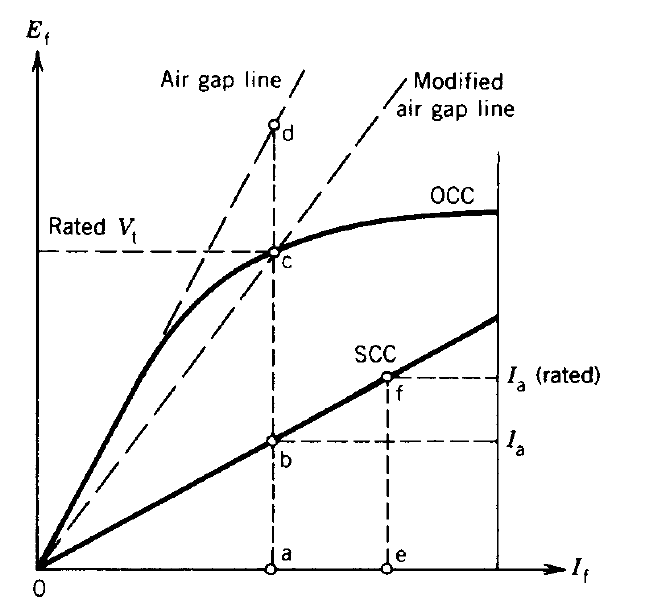
Use in Synchronous Reactance Calculation
Use in Synchronous Reactance Calculation
Using OCC and SCC:
\( X_s = \frac{E_{oc}}{I_{sc}} \)
Where:
- \( E_{oc} \) = Open circuit voltage
- \( I_{sc} \) = Short circuit current