Table of Contents
The Role of Inductance ($L$)
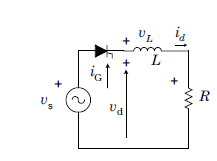
In a purely resistive load, the current stops exactly when the voltage reaches zero. However, an Inductor ($L$) opposes any change in current. It stores energy during the positive half-cycle and releases it when the source voltage begins to fall, forcing the Thyristor (SCR) to continue conducting even after the input voltage goes negative.
Principle of Operation
The operation is defined by three critical angles: the firing angle ($\alpha$), the extinction angle ($\beta$), and the conduction angle ($\gamma$).
The Conduction Phase ($\alpha$ to $\pi$)
When the SCR is triggered at $\omega t = \alpha$, the load current $i_o$ starts to increase. Because of the inductor, the current lags behind the voltage and reaches its peak after the voltage peak.
The Extension Phase ($\pi$ to $\beta$)
At $\omega t = \pi$, the source voltage becomes negative. In a resistive load, the SCR would turn off here. But in an RL load, the inductor’s stored energy maintains the current flow. The SCR remains ON until the current finally drops to zero at the extinction angle ($\beta$).
The Thyristor is in conducting mode even the supply voltage is negative as the load current is higher than the holding current. The load current lags behind the supply voltage due to inductive load.
Mathematical Analysis
The presence of the negative voltage “tail” reduces the overall average DC output compared to a purely resistive load.
Average Output Voltage ($V_{dc}$):
The integration now extends from $\alpha$ to $\beta$:
$$V_{dc} = \frac{1}{2\pi} \int_{\alpha}^{\beta} V_m \sin(\omega t) \, d(\omega t) = \frac{V_m}{2\pi} (\cos \alpha – \cos \beta)$$
Conduction Angle ($\gamma$):
This is the total duration the SCR is conducting:
$$\gamma = \beta – \alpha$$
Instantaneous Current Equation ($i_o$):
The current consists of a steady-state (forced) component and a transient component:
$$i_o(\omega t) = \frac{V_m}{Z} \left[ \sin(\omega t – \phi) – \sin(\alpha – \phi) e^{-\frac{R}{L \omega}(\omega t – \alpha)} \right]$$
Where $Z = \sqrt{R^2 + (\omega L)^2}$ and $\phi = \tan^{-1}\left(\frac{\omega L}{R}\right)$.
Key Observations
- Negative Voltage: The output voltage becomes negative between $\pi$ and $\beta$, which lowers the average DC value.
- Discontinuous Current: In a half-wave circuit with RL load, the current is typically discontinuous because it must drop to zero before the next cycle starts.
- Effect of Inductance: Increasing $L$ increases the extinction angle $\beta$, making the “negative tail” larger and further reducing $V_{dc}$.
The Solution: Freewheeling Diode
To prevent the output voltage from going negative and to improve efficiency, a Freewheeling Diode (FWD) is often connected in parallel with the RL load. This diode provides a path for the inductor current to circulate, allowing the SCR to turn off exactly at $\pi$.