Table of Contents
Principle of Step-Down Chopper
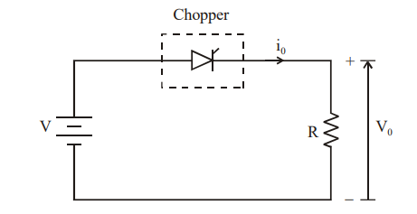
In a step-down chopper, the thyristor acts as an electronic switch. When the thyristor is turned ON, the supply voltage is directly applied across the load. When the thyristor is turned OFF, the load is disconnected from the supply, and the voltage across the load becomes zero.
Circuit Operation
The operation is divided into two distinct modes based on the state of the chopper (switch):
Mode 1: Chopper is ON (\(0 \le t \le T_{ON}\))
- Path: The DC source (\(V_s\)), the switch, and the R-L load form a closed loop.
- Action: The source supplies energy to the load. The inductor stores energy in its magnetic field.
- Current: The load current (\(i_o\)) rises exponentially from a minimum value (\(I_1\)) to a maximum value (\(I_2\)).
- Equation: \(V_s = R i_o + L \frac{di_o}{dt}\)
Mode 2: Chopper is OFF (\(T_{ON} \le t \le T\))
- Path: The switch is open. The inductor, resistor, and freewheeling diode (FD) form a closed loop.
- Action: The magnetic energy stored in the inductor is released. The inductor acts as a source, pushing current through the freewheeling diode.
- Current: The load current (\(i_o\)) decays exponentially from \(I_2\) back toward \(I_1\).
- Equation: \(0 = R i_o + L \frac{di_o}{dt}\)
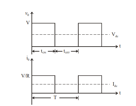
Waveform
The control methods for a step-down chopper aim to regulate the average output voltage by adjusting the duty cycle (\(\alpha = T_{ON} / T\)). There are two primary strategies: Time Ratio Control (TRC) and Current Limit Control (CLC).
Time Ratio Control (TRC)
In this method, the output voltage is adjusted by changing the ratio of ON-time (\(T_{ON}\)) to the total switching period (\(T\)). It is further divided into two techniques:
Constant Frequency System (Pulse Width Modulation – PWM):
-
- The total switching period (\(T\)) and frequency (\(f = 1/T\)) are kept constant.
- The ON-time (\(T_{ON}\)) is varied to change the duty cycle.
- Advantage: This is the most preferred scheme because it simplifies filter design and avoids interference with communication lines.
Variable Frequency System (Frequency Modulation – FM):
-
- Either the ON-time (\(T_{ON}\)) or the OFF-time (\(T_{OFF}\)) is kept constant.
- The total switching period (\(T\)) is varied, which changes the chopping frequency (\(f\)).
- Disadvantage: Wide frequency variations can lead to complex filter requirements and possible electromagnetic interference (EMI).
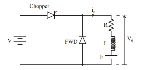
Step-down Chopper with an R-L load and Freewheeling Diode
In a step-down chopper with an R-L load (Resistor and Inductor), the inductor changes the behavior of the circuit by resisting sudden changes in current. This results in a “smoothing” effect where the load current does not drop to zero immediately when the switch is turned off.
Circuit Operation
The operation is divided into two distinct modes based on the state of the chopper (switch):
Mode 1: Chopper is ON (\(0 \le t \le T_{ON}\))
- Path: The DC source (\(V_s\)), the switch, and the R-L load form a closed loop.
- Action: The source supplies energy to the load. The inductor stores energy in its magnetic field.
- Current: The load current (\(i_o\)) rises exponentially from a minimum value (\(I_1\)) to a maximum value (\(I_2\)).
- Equation: \(V_s = R i_o + L \frac{di_o}{dt}\)
Mode 2: Chopper is OFF (\(T_{ON} \le t \le T\))
- Path: The switch is open. The inductor, resistor, and freewheeling diode (FD) form a closed loop.
- Action: The magnetic energy stored in the inductor is released. The inductor acts as a source, pushing current through the freewheeling diode.
- Current: The load current (\(i_o\)) decays exponentially from \(I_2\) back toward \(I_1\).
- Equation: \(0 = R i_o + L \frac{di_o}{dt}\)
Waveform
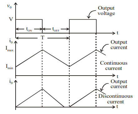
- Output Voltage (\(V_o\)): Still a rectangular pulse. It is \(V_s\) during \(T_{ON}\) and \(0\) during \(T_{OFF}\).
- Output Current (\(i_o\)): Unlike a purely resistive load (where current is a square wave), the R-L load current is triangular/sawtooth in shape.
- Continuous vs. Discontinuous Conduction:
- Continuous: The current never hits zero before the next cycle starts (common in high-frequency switching).
- Discontinuous: The current hits zero during \(T_{OFF}\) because the inductor is small or the frequency is too low.
Role of Inductor
The inductor acts as a low-pass filter. It reduces the “ripple” (fluctuation) in the current, which is critical for the smooth operation of DC motors to prevent overheating and mechanical vibration.
The heart of a step-down chopper circuit consists of several key semiconductor and passive components:
- Switching Device: Typically a high-speed semiconductor like a MOSFET or IGBT. This device rapidly turns the power supply on and off.
- Inductor ($L$): Connected in series with the load. It stores energy when the switch is ON and releases it when the switch is OFF, smoothing the output current.
- Freewheeling Diode ($D$): Provides a continuous path for the inductor current to flow when the main switch is OFF, preventing voltage spikes and ensuring stable power delivery.
- Capacitor ($C$): Often used in parallel with the load to filter out high-frequency ripples and stabilize the output voltage.
Working Principle
The operation occurs in two distinct modes based on the state of the switching device:
Mode 1: Switch ON ($T_{ON}$)
- The chopper switch is closed, connecting the source voltage ($V_s$) directly to the load.
- The inductor begins to store energy, and the output voltage ($V_o$) equals the input voltage ($V_s$).
- Current flows from the source through the inductor to the load.
Mode 2: Switch OFF ($T_{OFF}$)
- The switch is opened, disconnecting the source from the load.
- The inductor’s polarity reverses as it begins to discharge its stored energy.
- The freewheeling diode becomes forward-biased, allowing current to continue flowing through the load via the inductor-diode loop.
- The output voltage drops to zero during this interval.
Mathematical Formula
The average output voltage ($V_o$) is determined by the Duty Cycle ($\alpha$ or $D$), which is the ratio of the ON time to the total time period ($T$).
$$V_o = \alpha \times V_s = \left(\frac{T_{ON}}{T_{ON} + T_{OFF}}\right) \times V_s$$
By adjusting the duty cycle between 0 and 1, you can precisely control the output voltage from zero up to the source voltage.
Advantages
- High Efficiency: Unlike linear regulators that dissipate excess voltage as heat, choppers use switching to minimize energy loss.
- Precise Control: They allow for fine-tuned regulation of output voltage even if the input fluctuates.
- Compact Design: High-frequency operation allows for smaller inductors and capacitors, making the system lightweight.
Real-World Applications
Step-down choppers are vital in modern electronics, including:
- DC Motor Speed Control: Widely used in electric vehicles and industrial drives to regulate motor speed by varying armature voltage.
- Switch Mode Power Supplies (SMPS): Providing stable DC for computers and sensitive electronic devices.
- Battery Charging: Regulating the voltage levels required for charging various battery types safely.