In the world of power electronics, few components are as critical as the thyristor. Often described as a “controllable diode,” this solid-state semiconductor device acts as a high-speed, bistable switch capable of handling massive voltages and currents.
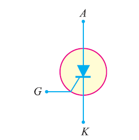
Table of Contents
What is a Thyristor?
A thyristor is a four-layer ($P-N-P-N$) semiconductor device with three junctions ($J_1, J_2,$ and $J_3$). While it looks similar to a transistor, its internal structure allows it to “latch” in an ON state, making it far more efficient for high-power switching.
Key Terminals:
- Anode ($A$): The positive terminal where current enters.
- Cathode ($K$): The negative terminal where current exits.
- Gate ($G$): The control terminal used to trigger the device into conduction.
How It Works: Operating Modes
A thyristor operates in three distinct states based on the bias applied to its junctions:
- Reverse Blocking Mode: The cathode is positive relative to the anode. Junctions $J_1$ and $J_3$ are reverse-biased, blocking current flow.
- Forward Blocking Mode: The anode is positive, but no gate signal is applied. Junction $J_2$ is reverse-biased, so the device remains “OFF” despite the forward pressure.
- Forward Conduction Mode: A small pulse is applied to the Gate. This breaks down the $J_2$ junction, allowing a large current to flow from anode to cathode.
The Latching Secret: Once triggered, the thyristor stays ON even if the gate signal is removed. It only turns OFF when the current drops below a specific threshold known as the Holding Current ($I_H$).
The Critical $dv/dt$ Effect
Because the reverse-biased junction $J_2$ acts like a capacitor ($C_{j2}$), a rapid change in voltage can create a charging current ($I_c$) even without a gate signal. This is defined by the equation:
$$I_c = C_{j2} \frac{dv}{dt}$$
If the rate of voltage rise ($\frac{dv}{dt}$) exceeds the critical limit, the resulting $I_c$ may be large enough to trigger the thyristor accidentally. This is why snubber circuits are used for protection.
Real-World Applications
- Motor Speed Control: Regulating heavy industrial motors.
- HVDC Transmission: Managing power across long-distance electrical grids.
- Household Appliances: Light dimmers and fan speed controllers.