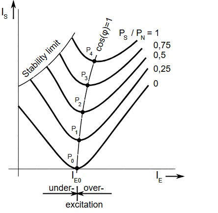
The V-curves of a synchronous motor represent the relationship between the armature current and the field excitation current when the motor operates at a constant load. These curves are called V-curves because the plot of armature current versus field current resembles the shape of the letter “V”.
V-curves are very important for understanding how field excitation affects current drawn by a synchronous motor. It also demonstrates how power factor of a synchronous motor can be controlled by adjusting excitation.
Table of Contents
Basic Concept
In a synchronous motor, the field current controls the excitation of the rotor. By varying the field current, the power factor and armature current of the motor can be adjusted. When the load on the motor is kept constant, the armature current changes as the field excitation is varied.
Axes of V-Curve
The V-curve graph is plotted as follows:
- X-axis: Field current (excitation current (I_f))
- Y-axis: Armature current ((I_a))
The resulting curve appears V-shaped.
Regions of Operation
The V-curve can be divided into three regions depending on the excitation level.
Under-Excited Region
In this region:
- Field current is less than the normal value
- Motor operates at lagging power factor
- Armature current is high
The motor behaves similar to an induction motor and absorbs reactive power from the supply.
Normal Excitation (Unity Power Factor)
At a particular field current:
- Power factor becomes unity
- Armature current becomes minimum
This point represents the lowest current drawn by the motor for a given load.
Over-Excited Region
In this region:
- Field current is greater than the normal value
- Motor operates at leading power factor
- Armature current increases again
The motor supplies reactive power to the system, acting like a synchronous condenser.
Shape of the V-Curve
As field current increases:
- Armature current initially decreases
- Reaches minimum at unity power factor
- Then increases again
Thus the plot forms a V-shaped curve.
Inverted V-Curve
Another important curve related to synchronous motors is the inverted V-curve.
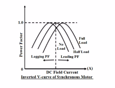
In this curve:
- X-axis: Field current
- Y-axis: Power factor
The curve shows:
- Lagging power factor in under-excitation
- Unity power factor at normal excitation
- Leading power factor in over-excitation
Effect of Load on V-Curves
For different load conditions, different V-curves are obtained.
Key observations:
- As load increases, the armature current increases
- The minimum point shifts slightly
- Multiple V-curves can be drawn for different load levels
These curves form a family of V-curves.
Practical Importance
V-curves are useful for:
- Determining the operating power factor
- Adjusting field excitation
- Understanding reactive power behavior
- Operating synchronous motors for power factor correction
Applications
The concept of V-curves is important in applications such as:
- Power factor correction in power systems
- Synchronous condensers
- Large industrial drives
- Power system stability control
Note: If the excitation of a synchronous motor is increased beyond the level corresponding to unity power factor, the motor operates at a leading power factor. This behavior is explained using the V-curve characteristic, which represents the relationship between armature current \(I_a\) and field current \(I_f\). When the motor is under-excited, it behaves like an inductor, draws reactive power from the supply, and operates at a lagging power factor. At normal excitation, the armature current becomes minimum and the motor operates at unity power factor. However, when the excitation is increased further (over-excitation), the motor behaves like a capacitor and begins to supply reactive power to the system, resulting in a leading power factor.
During over-excitation, the internal back EMF \(E_b\) increases and becomes greater than the applied terminal voltage \(V\). As a result, the motor supplies reactive power \(Q\) to the source, and the armature current \(I_a\) leads the terminal voltage \(V\). This leading current is responsible for the leading power factor condition. Due to this property, over-excited synchronous motors are commonly used as synchronous condensers in power systems. In such applications, the motor operates without mechanical load to provide leading reactive power, thereby improving the overall power factor of the system.