Power system protection is the process of detecting abnormal conditions in a power system and isolating the faulty section as quickly as possible while keeping the healthy part in operation.
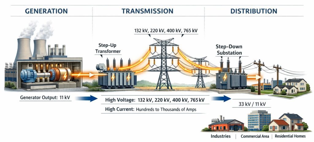
Table of Contents
What is a Power System?
A power system consists of generation, transmission, and distribution of electrical power. These systems operate at very high voltage levels, typically from 11 kV up to 765 kV, and carry very large currents ranging from hundreds to thousands of amperes. All electrical equipment such as generators, transformers, transmission lines, cables, and switchgear are designed to operate safely within their rated limits. However, when an abnormal condition occurs, the situation changes drastically.
What is Fault?
Faults such as short circuit, earth fault, overload, lightning strike, or insulation failure can cause the current to rise suddenly to ten to fifty times its normal value. Such a massive increase in current produces intense heating due to the square relationship between current and heat. It also creates very high mechanical forces because of strong electromagnetic effects. These stresses can damage insulation, deform conductors, crack winding supports, and severely disturb the stability of the entire system. The damage can begin within milliseconds.
Need of Protection Circuit
Without a protection system, the consequences are extremely serious. Transformers, generators, and cables may burn or even explode. Switchgear can fail violently. There is a significant fire hazard. A single fault may lead to a complete blackout of a city or even a large region. The financial loss can be enormous, and in some cases there can be danger to human life. In large interconnected grids, one uncleared fault can propagate and trigger a cascading failure.
The protection circuit has a very clear and focused job. It must detect the abnormal condition, determine whether it is a genuine fault, and isolate only the faulty portion of the system as quickly as possible. At the same time, it must ensure that the healthy parts of the system continue to operate normally. This concept is known as protection philosophy.
Features of a Protection System
A good protection system is designed based on five important principles. Reliability means it must operate correctly whenever a fault occurs. Selectivity means only the faulty section should be disconnected, not the entire network. Speed means the fault must be cleared as fast as possible to reduce damage and maintain stability. Sensitivity means the system should be able to detect even small fault currents within its protected zone. Economy means the protection scheme should provide maximum safety at reasonable cost without unnecessary complexity.
Therefore, protection circuits are not optional in power systems. They are essential for safe, stable, and continuous operation. In high voltage systems, faults are not small disturbances. They are potentially destructive events that must be cleared immediately to protect equipment, maintain supply continuity, and ensure public safety.
This is why power system protection is not merely a technical requirement—it is the backbone of every safe, reliable, and modern electrical power network.
What Is Power System Protection?
Power system protection is the collection of devices, schemes, and engineering practices designed to:
- Detect abnormal operating conditions or faults in an electrical power system, and
- Isolate the faulty section as quickly as possible, while
- Keeping the remaining healthy parts of the system in operation.
In simple terms, power system protection acts like the immune system of the power grid. When something goes wrong, it detects the problem, responds instantly, and prevents the fault from spreading and causing widespread damage.
Objectives of Power System Protection
The main objectives of any electrical protection system are:
- Safety: Protect personnel from hazards such as electric shock, arc flash, fire, and equipment explosions.
- Equipment Protection: Prevent damage to costly assets like generators, transformers, motors, cables, and switchgear.
- System Reliability: Ensure continuity of supply by disconnecting only the faulty section instead of the entire network.
- Continuity of Supply: Minimize outage duration and enable quick restoration of power.
- System Stability: Prevent local faults from escalating into large-scale blackouts or grid collapse.
Common Faults in Power Systems
A power system fault is any abnormal condition that disrupts the normal flow of current, voltage, or power. Understanding these faults is the foundation of effective protection design. In a three-phase electrical system, faults are broadly classified into symmetrical and unsymmetrical faults based on how they affect the three phases. This classification is important because the system behavior, fault currents, and protection methods differ significantly for each type.
Symmetrical Faults
A symmetrical fault is a fault in which all three phases are equally affected. The currents in the three phases are equal in magnitude and displaced by 120°, so the system remains electrically balanced even though very high fault current flows.
- Three-Phase Short-Circuit (LLL)
- Three-Phase-to-Ground Fault (LLLG)
Characteristics:
- Balanced three-phase currents and voltages
- Highest fault current magnitude
- Simple to analyze using per-phase equivalent circuits
- Causes severe thermal and mechanical stress on equipment
- Least frequent but most dangerous fault
Effect on the System:
- Sudden voltage collapse at the fault point
- Possible generator instability if not cleared quickly
- Major stress on circuit breakers and busbars
Protection Used:
- Differential protection
- Distance protection (Zone-1 for transmission lines)
- High-speed overcurrent protection
Unsymmetrical Faults
An unsymmetrical fault is a fault that affects one or two phases only, causing the system to become unbalanced. Phase currents and voltages are unequal and no longer separated by exactly 120°.
Types of Unsymmetrical Faults
(a) Single Line-to-Ground Fault (L-G)
- One phase makes contact with earth or grounded metal
- Most common fault (≈70% of all faults)
- Fault current depends on grounding method
Example: R-phase touching earth
(b) Line-to-Line Fault (L-L)
- Two phases short-circuited together
- No involvement of earth
- Fault current lower than three-phase fault
Example: R-phase shorted with Y-phase
(c) Double Line-to-Ground Fault (L-L-G)
- Two phases short-circuited and connected to earth
- More severe than L-L fault
- Produces high ground current
Example: R and Y phases touching earth
Characteristics of Unsymmetrical Faults
- Unbalanced currents and voltages
- Causes negative-sequence currents
- Results in overheating of generators and motors
- More complex analysis (requires symmetrical components)
Effect on the System
- Voltage unbalance leading to motor heating
- Torque pulsations in rotating machines
- Maloperation of sensitive equipment
Protection Used
- Earth fault relays
- Negative sequence relays
- Phase overcurrent protection
Comparison: Symmetrical vs Unsymmetrical Faults
| Aspect | Symmetrical Fault | Unsymmetrical Fault |
|---|---|---|
| Phases involved | All three | One or two |
| System balance | Balanced | Unbalanced |
| Fault current | Very high | Lower than symmetrical |
| Frequency of occurrence | Rare | Very common |
| Analysis method | Per-phase analysis | Symmetrical components |
| Damage severity | Very high | Moderate to high |
Why This Classification Is Important
- Determines relay type selection
- Helps in fault current calculation
- Essential for protection coordination
- Critical for equipment rating and stability studies
Key Takeaway
- Symmetrical faults are rare but extremely severe.
- Unsymmetrical faults are common and cause system unbalance.
- Both types must be detected and cleared rapidly to ensure safety, reliability, and stability of a three-phase power system.
If you want, I can also:
- Explain this using phasor diagrams
- Provide numerical examples
- Convert this into exam-ready short notes
- Create an illustrated fault-type diagram prompt
Types of Power System Faults
- Short-Circuit Fault:
Occurs when conductors at different electrical potentials come into direct contact, causing extremely high currents. These faults may be:- Three-phase faults
- Single-phase-to-ground faults
- Phase-to-phase faults
- Double-phase-to-ground faults
- Overcurrent Fault:
Happens when current exceeds the rated value of equipment, due to short circuits, overloads, or insulation failure. - Earth (Ground) Fault:
Occurs when a live conductor touches earth or grounded metal parts. Even low earth-fault currents can be dangerous. - Overload:
Not a sudden fault, but a sustained condition where equipment carries more current than its rated capacity, leading to overheating and insulation deterioration. - Open-Circuit Fault:
Results from broken conductors or loose connections, interrupting current flow and causing malfunction of equipment. - Voltage Unbalance:
Unequal phase voltages in three-phase systems can cause overheating and reduced life of motors and transformers.
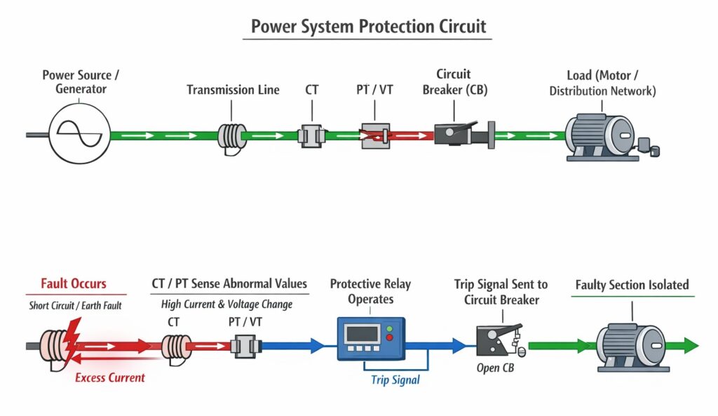
Key Components of a Power System Protection System
A complete protection system consists of several interconnected components, each with a specific role.
1. Current Transformers (CTs)
Current Transformers step down high system currents to safe, standardized values (typically 1 A or 5 A) for relays and meters. Accurate CT performance is critical—incorrect CT behavior can lead to false tripping or failure to trip during faults.
2. Potential Transformers (PTs) / Voltage Transformers (VTs)
PTs or VTs reduce high system voltages to safe levels (commonly 110 V or 63.5 V). They supply voltage inputs to protective relays, meters, and control circuits and are essential for voltage- and impedance-based protection schemes.
3. Protective Relays
Protective relays are the decision-making units of the protection system. They continuously monitor electrical parameters such as current, voltage, power, frequency, and impedance.
When a relay detects an abnormal condition exceeding its preset threshold, it issues a trip command to the circuit breaker.
Types of protective relays include:
- Electromechanical Relays: Traditional, robust, but slower and less flexible
- Static Relays: Electronic-based, faster than electromechanical relays
- Digital/Numerical Relays: Microprocessor-based, highly accurate, with communication, self-diagnostics, and fault recording—the industry standard today
4. Circuit Breakers
Circuit breakers are the actual fault-clearing devices. Upon receiving a trip signal from the relay, they open their contacts and interrupt the fault current safely. Circuit breakers are rated by their breaking capacity (kA) and must withstand severe electrical and mechanical stresses.
5. Protection Schemes and Signaling
A protection scheme defines how different relays, CTs, VTs, and circuit breakers are coordinated. Well-designed schemes ensure:
- Fast fault clearance
- Selective isolation
- Reliable backup protection if primary protection fails
Types of Power System Protection
Different equipment and fault conditions require different protection philosophies.
1. Overcurrent Protection
Overcurrent protection operates when current exceeds a preset value. Most relays use Inverse Definite Minimum Time (IDMT) characteristics—higher fault current results in faster operation.
Applications: Distribution feeders, radial networks, backup protection for transmission lines.
2. Differential Protection
Differential protection compares incoming and outgoing currents of equipment. Any difference indicates an internal fault and causes instantaneous tripping.
Applications: Power transformers, generators, busbars, large motors.
3. Distance Protection
Distance (impedance) protection measures the impedance between the relay and the fault point. Since impedance is proportional to distance, the relay determines fault location using zones:
- Zone 1: 80–85% of the line, instantaneous
- Zone 2: Up to 120%, time-delayed
- Zone 3: Backup protection, longer delay
Applications: High-voltage and extra-high-voltage transmission lines.
4. Earth Fault Protection
Earth fault protection detects faults between live conductors and earth, especially important in systems with limited fault current.
Applications: Distribution systems, industrial plants, motors, generators.
5. Voltage and Frequency Protection
These relays protect equipment against abnormal voltage and frequency conditions that can arise during grid disturbances, load rejection, or generation imbalance.
Real-World Applications of Power System Protection
- Generator Protection: Differential protection, loss of excitation, reverse power, stator and rotor earth faults
- Transformer Protection: Differential protection, overcurrent backup, Buchholz relay
- Transmission Line Protection: Distance protection with communication-assisted schemes
- Motor Protection: Overload, phase loss, locked rotor, earth fault
- Busbar Protection: High-speed differential protection for critical substation nodes
Protection Coordination: Getting It Right
Protection coordination ensures that the relay nearest to the fault trips first, while upstream relays act only as backup. Poor coordination can cause unnecessary outages, equipment damage, and cascading failures.
Coordination studies are commonly performed using professional software tools such as ETAP, DIgSILENT PowerFactory, and SKM.
Modern Trends in Power System Protection
- Digital and numerical relays with IEC 61850 communication
- Wide Area Protection Systems (WAPS) using synchronized measurements
- Adaptive protection for renewable-rich grids
- Increased focus on cybersecurity in substations
Summary
Power system protection is a critical engineering discipline that ensures safety, reliability, and continuity of electrical power supply. From overcurrent relays on distribution feeders to differential protection on generators and transformers, every part of the power system is continuously monitored and protected.
As modern power systems evolve with smart grids, renewable energy integration, and digital substations, the role of well-designed and well-coordinated protection systems becomes even more important. For students and beginners, mastering these fundamentals is a vital step toward a successful career in electrical power engineering.